A two-way stirring medium-pressure jet variable-diameter stirring pile drill pipe head

A two-way mixing, drill pipe head technology, applied in drill bits, sheet pile walls, earthwork drilling and other directions, can solve the problems of complex structure, inability to change the angle of shotcrete, unfavorable uniform mixing of pile foundations, etc., to achieve simple structure, grouting uniform effect

Active Publication Date: 2019-01-22
宁波越兴建设工程有限公司
View PDF3 Cites 0 Cited by
  • Summary
  • Abstract
  • Description
  • Claims
  • Application Information

AI Technical Summary

Problems solved by technology

[0003] In the prior art, the drill bit applied to the two-way stirring variable-diameter stirring pile is usually complex in structure, and the spraying angle cannot be changed, so it is not conducive to the uniform mixing of the pile foundation

Method used


Image

  • A two-way stirring medium-pressure jet variable-diameter stirring pile drill pipe head
  • A two-way stirring medium-pressure jet variable-diameter stirring pile drill pipe head
  • A two-way stirring medium-pressure jet variable-diameter stirring pile drill pipe head

Examples


Embodiment Construction

[0032] Embodiments of the present invention will be further described in detail below in conjunction with the accompanying drawings.

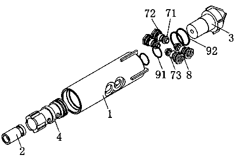
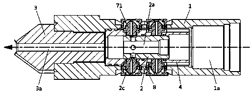
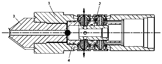
[0033] Figure 1 to Figure 17 It is a structural schematic diagram of an embodiment of the present invention.

[0034] The reference signs are: drill bit connection thread A, drill pipe connection thread B, positioning hole K, drill sleeve 1, three-step connection hole 1a, inner sleeve assembly hole 1b, drill step assembly hole 1c, positioning ring platform 1d, clip Spring groove 1e, piston 2, grouting channel 2a, grouting channel 2b, radial communication hole 2c, drill bit 3, grouting channel 3a, inner sleeve 4, sliding chamber 4a, limiting annular platform 4b, first sealing groove 4c, second sealing groove 4d, spline groove 4e, annular boss 4f, lower nozzle installation hole 5, upper nozzle installation hole 6, internal thread 6a, ball joint 71, external thread 71a, flow channel 71b, spherical body 71c, 90 Degree joint 72, 45 degree joint 7...


PUM


Abstract

The invention discloses a bidirectional stirring medium-pressure injection reducing stirring pile drill rod head. The drill rod head comprises a drill sleeve capable of being connected with a drill rod and a drill bit mounted at the front end of the drill sleeve, wherein a grouting hole channel is machined at the front end of the drill bit. An inner sleeve is assembled in the drill sleeve. A piston is arranged in a sliding cavity of the inner sleeve in a sliding fit manner. An axial grouting channel enabling grout for injection to be conveyed to the grouting hole channel is machined on the piston. A grouting groove channel is annularly machined in the outer circumferential face of the piston. At least two radial communicating holes used for enabling the grouting groove channel to communicate with the grouting channel in the radial direction are machined in the grouting groove channel in an equal radian manner. The outer circumferential face of the inner sleeve is provided with a plurality of nozzle mounting holes communicating with the sliding cavity of the inner sleeve in the radial direction. A nozzle used for grout injection is mounted on each nozzle mounting hole. A locating hole capable of allowing the corresponding nozzle to penetrate so as to facilitate injection is formed in the position, corresponding to each nozzle, of the drill sleeve. According to the drill rod head, opening and closing of the corresponding nozzles are controlled by means of sliding displacement of the piston in the sliding cavity of the inner sleeve, and rotary spraying injection of the grout in different directions and at different heights is achieved.

Description

technical field [0001] The invention relates to a drill pipe head, in particular to a drill pipe head for a variable-diameter stirring pile used in the treatment of soft soil foundations in construction sites, in particular to a drill pipe head for a variable-diameter stirring pile with two-way stirring medium-pressure injection. Background technique [0002] The two-way mixing adopts concentric two-axis drill pipes, the inner drill pipes rotate the blades forward, and the outer drill pipes rotate the blades reversely, and the cement soil is mixed in two directions at the same time. [0003] In the prior art, the drill bit applied to the two-way mixing variable-diameter mixing pile usually has a complex structure and cannot change the spraying angle, so it is not conducive to the uniform mixing of the pile foundation. Contents of the invention [0004] The technical problem to be solved by the present invention is to provide a two-way stirring medium-pressure spray variabl...

Claims


Application Information

Patent Timeline
Patent Type & Authority Patents(China)
IPC IPC(8): E21B10/60
CPCE02D5/46E21B10/60
Inventor 董宏波吴伟松
Owner 宁波越兴建设工程有限公司
Why Eureka
Try Eureka