
Reinforced bearing cooling device

A technology for heat sinks and bearings, applied in bearing components, shafts and bearings, bearing cooling, etc., can solve problems such as unfavorable long-term reliable and stable operation of bearings, low lubricating oil fluidity, and thinning of dynamic pressure oil film.

Active Publication Date: 2017-06-09
HUNAN CHONGDE IND TECH
View PDF5 Cites 3 Cited by
  • Summary
  • Abstract
  • Description
  • Claims
  • Application Information

AI Technical Summary

Problems solved by technology

During use, when running at low speed, the fluidity of the lubricating oil inside the oil tank is low, and the hot oil does not have enough power to flow to the cooler for cooling. In this way, the hot oil continues to participate in lubrication to form a short circuit, and the dynamic pressure oil film becomes thinner, which is not conducive to Long-term reliable and stable operation of bearings

Method used


Image

  • Reinforced bearing cooling device
  • Reinforced bearing cooling device
  • Reinforced bearing cooling device

Examples


Embodiment Construction

[0025] The purpose of the present invention is to provide a heat dissipation device for strengthening bearings, which has a simple structure and effectively enhances cooling efficiency.

[0026] In order to enable those skilled in the art to better understand the technical solutions of the present invention, the present invention will be further described in detail below in conjunction with the accompanying drawings and specific embodiments. It should be noted that, in the case of no conflict, the embodiments in the present application and the features in the embodiments can be combined with each other.

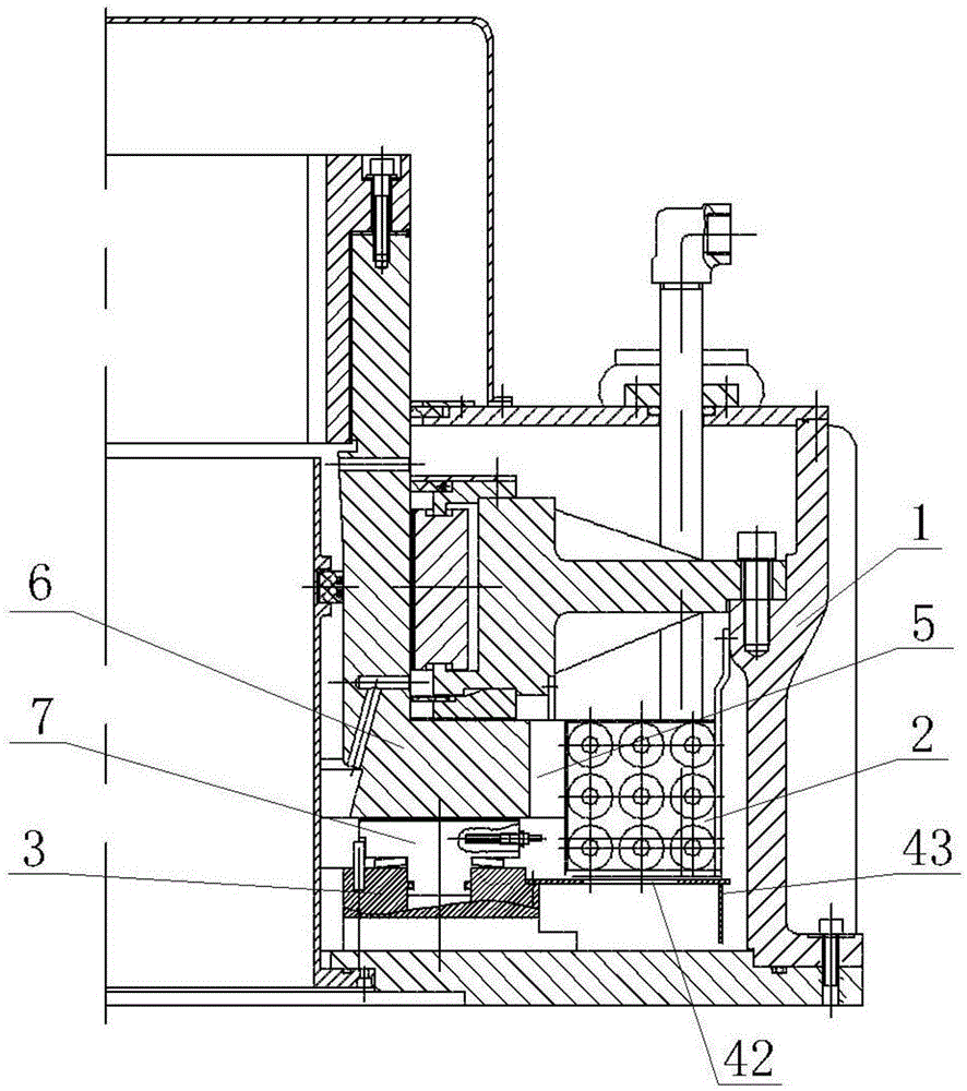
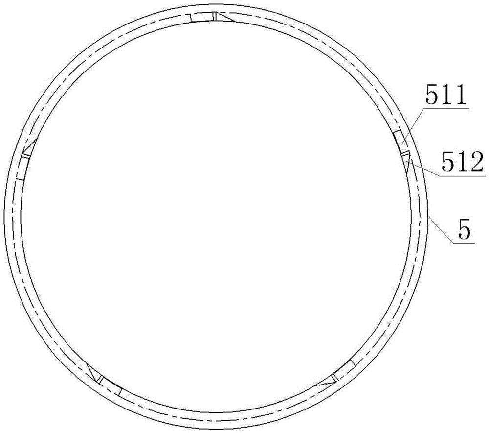
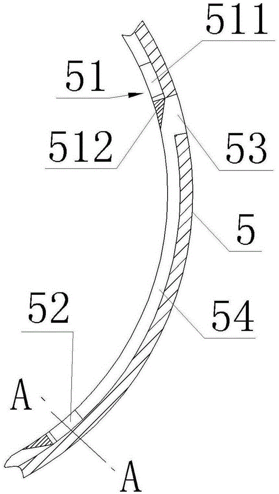
[0027] In a specific embodiment, such as Figure 1 to Figure 6 As shown, the present invention provides a bearing heat dissipation device, including: a bearing oil tank 1, a thrust head 6 disposed in the bearing oil tank 1 for transmitting axial force from the main shaft to the bearing mirror plate, and a thrust head 6 disposed in the bearing oil tank 1 The inner cooler 2, b...


PUM


Abstract

The invention discloses a reinforced bearing cooling device. The device comprises a bearing oil tank, a thrust head which is arranged in the bearing oil tank and used for transmitting axial force to a bearing lens plate from a spindle, a cooler and a bearing plate, wherein the cooler and the bearing plate are arranged in the bearing oil tank; an oil guide chamber is arranged at the position, between the thrust head and the cooler, of the outer circle of the thrust head, and is wholly in a circular ring shape, a plurality of guide pieces are arranged on the inner side wall of the oil guide chamber in a surrounding manner and comprises blades and triangular supports connected with the blades together, the blades and the triangular supports are arranged in the circumferential direction, an oil path channel is formed among blades and the triangular supports of every two adjacent guide pieces, oil inlets are formed in one ends of the blades, oil outlets are formed in one ends of the triangular supports, openings of the oil inlets are formed in the upper ends and the lower ends of the corresponding blades, and are formed upwards and downwards in the axial direction of the oil guide chamber, and the oil outlets are formed towards the outer side of the oil guide chamber. The reinforced bearing cooling device is simple in structure and convenient to mount, and the cooling efficiency can be effectively improved.

Description

technical field [0001] The invention relates to the technical field of bearing conduction and heat dissipation, in particular to a device for strengthening heat dissipation of a bearing. Background technique [0002] At present, most vertical sliding bearings are self-lubricating bearings. The lubricating oil inside the bearing does not depend on the outside, and only the internal mechanical structure of the bearing obtains the circulating power. During use, when running at low speed, the fluidity of the lubricating oil inside the oil tank is low, and the hot oil does not have enough power to flow to the cooler for cooling. In this way, the hot oil continues to participate in lubrication to form a short circuit, and the dynamic pressure oil film becomes thinner, which is not conducive to Bearings run reliably and stably for a long time. [0003] Therefore, strengthening the guidance and dredging of the lubricating oil circuit inside the bearing at low speed is a more feasib...

Claims


Application Information

Patent Timeline
Patent Type & Authority Applications(China)
IPC IPC(8): F16C37/00
Inventor 刘小军周欣骄周少华罗碧朱杰
Owner HUNAN CHONGDE IND TECH
Learn More