Sheath used for driving shaft, driving shaft and vehicle

A drive shaft and sheath technology, applied in the vehicle field, can solve problems such as sheath damage, sheath damage, and sheath rupture, and achieve the effects of improving endurance, reducing impact force and abnormal noise, and improving performance

Active Publication Date: 2017-06-09
GREAT WALL MOTOR CO LTD
View PDF7 Cites 2 Cited by
  • Summary
  • Abstract
  • Description
  • Claims
  • Application Information

AI Technical Summary

Problems solved by technology

Due to the design and manufacturing tolerances of the parts between the drive shaft, the wheel and the transmission, and the components of the drive shaft itself, there is a large torsional gap between the components in the radial direction, and there is also a play gap in the axial direction , the gap increases after dynamic load torque transmission or component wear, resulting in a greatly reduced NVH performance of the system
[0003] In addition, in the existing drive shaft structure, the two ends of the shaft rod are respectively connected to the corresponding fixed joints and moving joints through rubber sheaths with a tapered structure, and the two ends of the rubber sheath are fastened by clamps, and the rubber The sleeve wall of the sheath is formed in a corrugated shape
In this way, due to the large amount of thermal deformation of the rubber material, for example, in the case of poor control of the internal cavity pressure of the moving joint, it is easy to cause the internal pressure of the cavity to be too large or too small, which will cause the shaft and the telescopic components in the cavity to be stretched during the stretching process. There is a risk that the sheath is sunken or the pressure is too high to cause the sheath to rupture. In addition, in the actual assembly process of this kind of sheath, the telescopic component is prone to the problem of detaching from the cage shell. During the process of detachment and restoration, there are Extrusion or damage to the sheath will cause early failure or wear of the sheath. In addition, the material of the sheath of the existing structure is only designed to be rubber, which has weak resistance to external damage. Damage to the sheath and oil leakage

Method used


Image

  • Sheath used for driving shaft, driving shaft and vehicle
  • Sheath used for driving shaft, driving shaft and vehicle
  • Sheath used for driving shaft, driving shaft and vehicle

Examples


Embodiment Construction

[0027] It should be noted that, in the case of no conflict, the embodiments of the present invention and the features in the embodiments can be combined with each other.

[0028] The present invention will be described in detail below with reference to the accompanying drawings and examples.

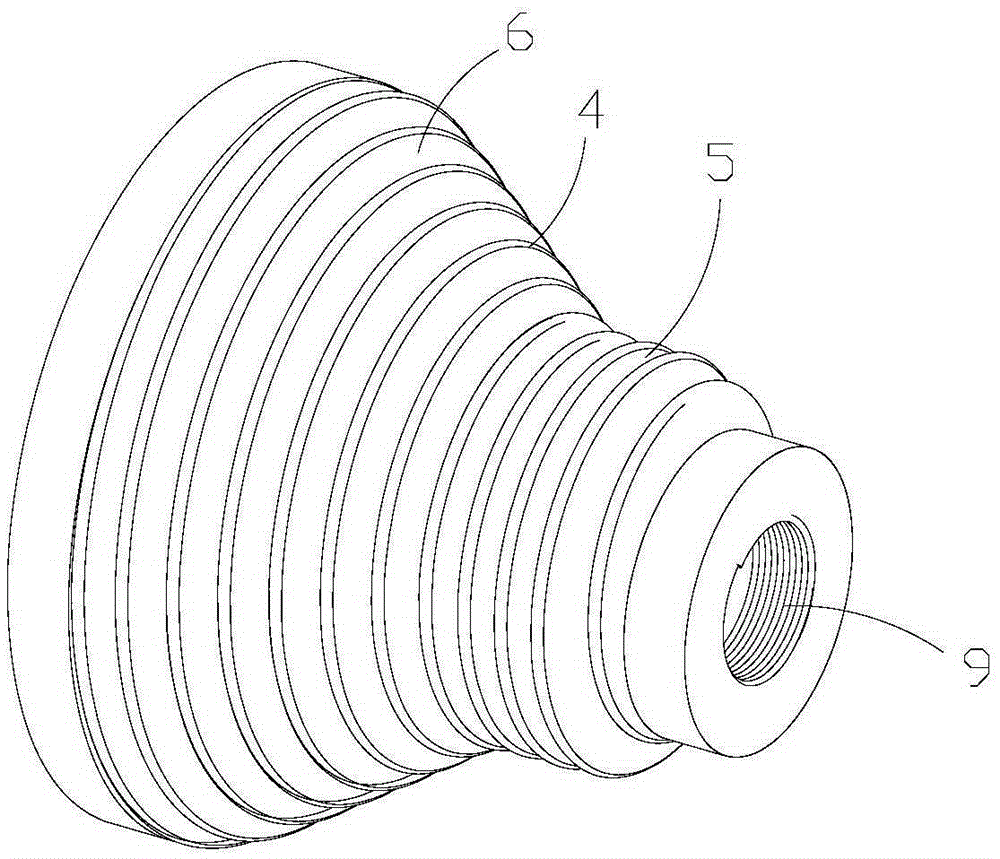
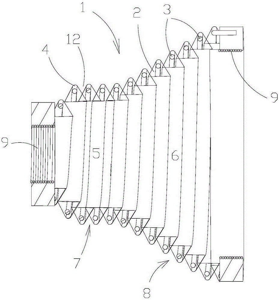
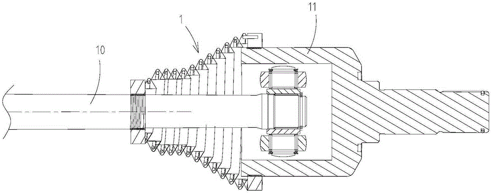
[0029] figure 1 and 2 A sheath for a drive shaft provided by an embodiment of the invention is shown. Such as figure 1 and 2 As shown, the sheath 1 of the present invention has an overall axially extending sleeve wall 2, the sheath 1 can be the same as the existing drive shaft sheath, and at the same time, the sleeve wall 2 of the sheath 1 provided by the present invention is provided with a shaft Extended coil spring 3.

[0030] Like this, through this technical solution, since the sleeve wall 2 of sheath 1 is provided with the helical spring 3 that extends axially, like this, by this helical spring 3, in practical application, after initial assembly, for example, has this helical ...


PUM


Abstract

The invention relates to the technical field of drive shafts of vehicles, and provides a sheath used for a driving shaft, the driving shaft and a vehicle. The sheath used for the driving shaft includes a sheath wall, the whole sheath wall extends in the axial direction, the sheath wall is provided with a spiral spring extending in the axial direction so as to effectively absorb impact and abnormal sound noise generated by the driving shaft due to radial clearances and axial clearances in the torque transmission and movement processes, and therefore the performance of the vehicle can be improved.

Description

technical field [0001] The invention relates to the technical field of vehicle drive shafts, in particular to a sheath for a drive shaft, a drive shaft with the sheath, and a vehicle. Background technique [0002] As people's requirements for vehicle driving system and NVH performance are getting higher and higher, the performance design of various parts of the vehicle chassis is also continuously improved. It is known that the drive shaft is a non-negligible component in the optimization and improvement of vehicle powertrain and NVH performance. The drive shaft usually includes a constant velocity universal joint designed as a six-ball fixed joint (hereinafter referred to as the fixed joint), a three-ball pin type telescopic constant velocity joint (hereinafter referred to as the movable joint) and a shaft rod. Among them, the fixed joint It is connected with the wheel end, the movable joint is connected with the transmission end, and the drive shaft transmits the output t...

Claims


Application Information

Patent Timeline
Patent Type & Authority Applications(China)
IPC IPC(8): F16D3/84
Inventor 王庚川杨鸿展孙玉梁延召张英富杜阿雷刘亚明金宇
Owner GREAT WALL MOTOR CO LTD
Why Eureka
Try Eureka