Gantry type device for performing multidimensional measurement on finely-machined component
A multi-dimensional, gantry-type technology, applied in measurement devices, instruments, etc., can solve the problems of large influence of deformation on measurement accuracy, and achieve the effect of small bending deformation and favorable measurement accuracy.
- Summary
- Abstract
- Description
- Claims
- Application Information
AI Technical Summary
Problems solved by technology
Method used
Image

Examples
Embodiment 1
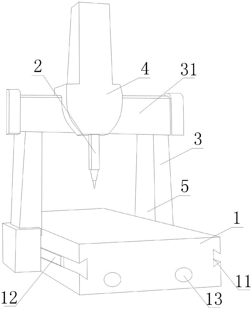
[0019] Such as figure 1 As shown, a gantry-type device for multi-dimensional measurement of finished parts includes a base 1 on which two parallel chutes 11 are arranged, and sliders 12 are arranged in the chutes 11 , also includes a door frame 3 in the shape of a door frame, the door frame 3 includes columns at both ends and a beam 31 between the columns, the free ends of the columns are respectively fixed on a slider 12, the The beam 31 is also provided with a sliding part 4 that can slide along the length direction of the beam 31 , and the measuring head 2 is fixed on the sliding part 4 .
[0020] In the present embodiment, the arm of measuring device is set to the structural form of gantry 3, like this, in the process that sliding part 4 moves on crossbeam 31, the two ends of crossbeam 31 are respectively supported by a column, like this, The crossbeam 31 is equivalent to a beam with both ends fixed. Compared with the structure of the existing cantilever beam used to bea...
Embodiment 2
[0022] The present embodiment is further limited on the basis of embodiment 1, as figure 1 As shown, as a specific implementation form of the chute 11 that is convenient for respectively defining the position of the slider 12 , the chute 11 is a dovetail groove whose outer width is smaller than the inner width.
[0023] In order to use the upper surface of the base 1 to place the measured object as much as possible, the two sliding slots 11 are respectively located on different sides of the base 1 .
[0024] In order to facilitate hoisting of the base 1 , hoisting holes 13 are also provided on the base 1 .
[0025] As a realization form of the hoisting hole 13 which is convenient for the hoisting lock to pass through, the length direction of the hoisting hole 13 is located in the length direction or the width direction of the base 1 .
Embodiment 3
[0027] This embodiment is further defined on the basis of any one of the solutions provided in the above embodiments, as a technical solution that facilitates the linear adjustment of the sliders 12 respectively in the chute 11, and the sliders 12 are threaded A threaded rod is attached to brake the movement of both.
PUM
 Abstract
Description
Claims
Application Information
 - R&D
- Intellectual Property
- Life Sciences
- Materials
- Tech Scout
- Unparalleled Data Quality
- Higher Quality Content
- 60% Fewer Hallucinations
Browse by: Latest US Patents, China's latest patents, Technical Efficacy Thesaurus, Application Domain, Technology Topic, Popular Technical Reports.
© 2025 PatSnap. All rights reserved.Legal|Privacy policy|Modern Slavery Act Transparency Statement|Sitemap|About US| Contact US: help@patsnap.com