
Laser processing device for crankshaft and method for performing laser processing on crankshaft

A laser processing and crankshaft technology, applied in auxiliary devices, metal processing, laser welding equipment, etc., can solve the problems of reduced efficiency and precision of laser processing, insignificant processing effect, and difficulty in adjusting the rotation axis. Realize laser processing, reduce bending deformation, and improve the effect of installation

Inactive Publication Date: 2016-06-22
JIANGSU UNIV
View PDF6 Cites 12 Cited by
  • Summary
  • Abstract
  • Description
  • Claims
  • Application Information

AI Technical Summary

Problems solved by technology

At present, in the field of laser processing, the new positioning and clamping device used in the new crankshaft laser processing device is a new five-coordinate linkage device, but the accuracy is not very high.
Especially due to the special structure of the crankshaft, the main shaft journal and the connecting rod shaft journal are not on the same center line, it is difficult to realize the adjustment of the rotation axis of the crankshaft main shaft journal and the connecting rod shaft journal during processing, making laser processing The efficiency and accuracy of processing are greatly reduced
In addition, in the process of laser processing of the crankshaft, there are still problems such as bending deformation of the crankshaft, low precision of the processing device, uneven processing, and inconspicuous processing effects.

Method used


Image

  • Laser processing device for crankshaft and method for performing laser processing on crankshaft

Examples


Embodiment Construction

[0016] The present invention will be further described in detail below with reference to the embodiments of the accompanying drawings.

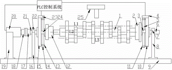
[0017] Such as figure 1 As shown, the novel device for crankshaft laser processing includes a laser 25 and a workbench 9, the two ends of the workbench 9 are equipped with a first support 8 and a second support 16, and the top of the first support 8 is provided with The first bearing 7, the first transmission shaft 6 is connected with the rotation pair of the first support through the first bearing 7; the top of the second support 16 is provided with a second bearing 22, and the second transmission shaft 21 passes through the first support The second bearing 22 is connected with the rotation pair of the second bearing 16;

[0018] The first transmission shaft 6 is fixedly equipped with a first guide post 10, the upper end of the first guide post 10 is provided with a first stepper motor 4, the lower end is provided with a first screw support...


PUM


Abstract

The invention relates to a laser processing device for a crankshaft and a method for performing laser processing on the crankshaft. The laser processing device comprises the crankshaft, a three-claw clamping disk, sliding blocks, a stepping motor, a ball screw, a bearing, a support, a workbench, a guide column, a screw support, a support, a shaft coupler, a motor support, a second stepping motor, a transmission shaft, a second bearing and a laser device. The laser processing device for the crankshaft is used for performing laser processing on the crankshaft, so that the rotating axes of a main shaft neck and a connecting rod shaft neck of the crankshaft can be adjusted more precisely; meanwhile, a PLC control system is adopted to more precisely control the rotating angles of the three stepping motors and the displacements of the two sliding blocks, so that the rotating error can be reduced, and the processing precision is improved; the aim of precise laser processing of the main shaft neck and the connecting rod shaft neck of the crankshaft is fulfilled.

Description

technical field [0001] The invention relates to the technical field of laser machining crankshafts, in particular to a crankshaft laser machining device and a crankshaft laser machining method. Background technique [0002] The vigorous development of the automobile industry has put forward higher requirements and expectations for the automobile manufacturing industry. The new generation of national IV / V emission standard vehicles requires better safety, higher operational reliability, more environmental protection, and more intelligence. As the core component of the whole car, the engine has a decisive influence on the running reliability and performance of the car. The crankshaft is the part with the most concentrated stress and the most complicated stress of the automobile engine, and it is also the part most prone to problems. The quality of the crankshaft directly determines the overall quality of the engine. The failure modes of the crankshaft are mainly journal wear ...

Claims


Application Information

Patent Timeline
Patent Type & Authority Applications(China)
IPC IPC(8): B23K26/70B23K37/04B23K26/352
CPCB23K26/352B23K26/356B23K26/70B23K37/0443B23K2101/006
Inventor 任旭东叶召李琳任云鹏佟艳群周睿胡征征
Owner JIANGSU UNIV
Learn More