A device and method for measuring film strain and thermal conductivity

A technology of thermal conductivity and thin film, applied in the field of MEMS device devices of micro-electromechanical systems, can solve the problems of complex, unequal, and unsatisfactory devices, and achieve the effects of easy operation, simple structure, mature and reliable

Active Publication Date: 2019-04-12
XI AN JIAOTONG UNIV +1
View PDF17 Cites 0 Cited by
  • Summary
  • Abstract
  • Description
  • Claims
  • Application Information

AI Technical Summary

Problems solved by technology

[0003] For example, in the patent (authorized announcement number CN 103822736 B) "a method for determining the strain value of the film under the concentrated force of the circular film clamped around the periphery" (He Xiaoting, Sun Junyi, Zheng Zhoulian, Cai Zhenhong, etc.), a frictionless flat bottom is used. The cylinder is used as the loading axis, and a transverse load is applied at the center of the circular film. By this method, the stress value of the film at a certain point can be obtained. Different radii correspond to different stress values, that is, different strains, but this method is different. The strain at the radius is not equal, which cannot meet our demand for strain; for example, in the patent (authorized announcement number CN 102001617B) "A Displacement Loading Device and Method for Flexible Electronic Devices" (Feng Xue, Jiang Dongjie, Wang Yong) , elaborated in detail the method of using DC power supply, brackets, guide rails, springs, etc. to achieve the required strain of the film. By controlling the magnitude of the DC current, the magnitude of the strain can be obtained indirectly. The strain obtained by this method is not linear, and the device Complicated, still can not meet the needs

Method used


Image

  • A device and method for measuring film strain and thermal conductivity
  • A device and method for measuring film strain and thermal conductivity
  • A device and method for measuring film strain and thermal conductivity

Examples


Embodiment Construction

[0030] The invention will be further described in detail below in conjunction with the accompanying drawings and embodiments, but it is not used as a basis for any limitation on the invention.

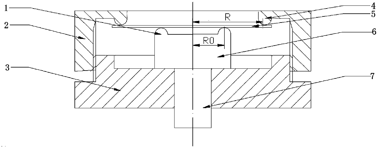
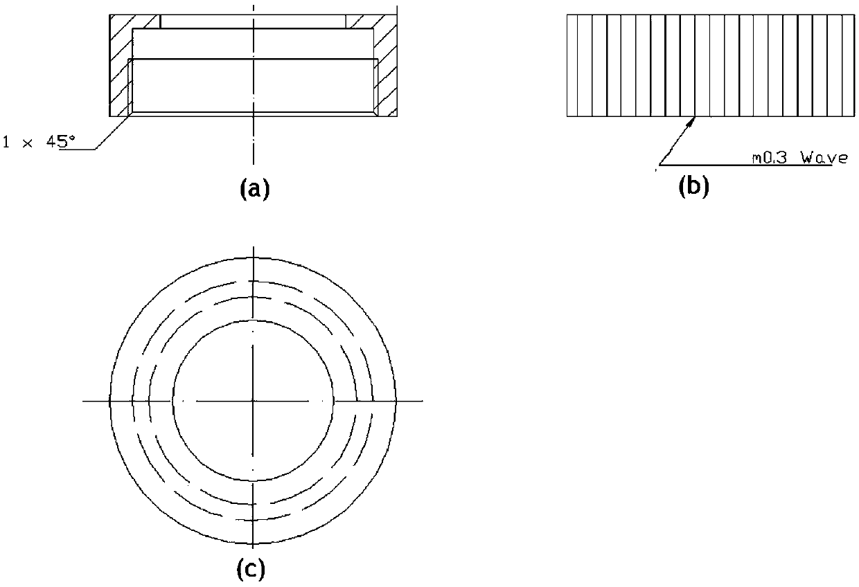
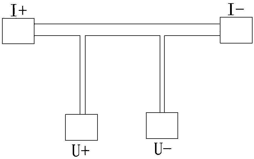
[0031] Such as figure 1 , figure 2 Shown in (a)-(c), the device for measuring thin film strain and thermal conductivity of the present invention includes a base 3, a shell 2 arranged on the base 3, the base 3 is provided with a loading end 6, coated with a thin film The substrate 5 is placed on the loading end 6 and connected to the simply supported fixed end 4 on the upper part of the housing 2, a precision guide rod 7 is provided under the loading end 6, and a test electrode and a metal plate are sputtered on the substrate 5 coated with a thin film. The test electrode is connected to the detection system with an external lock-in amplifier module and connected to the computer; the precession displacement S of the precision guide rod 7 makes the film on the substrate 5 coated with th...


PUM


Abstract

The invention discloses a device and a method of measuring film strain and thermal conductivity. The device comprises a base, a housing disposed on the base, and a loading end disposed on the base. A film sample is disposed on the loading end, and is connected with a simply supported fixed end disposed on the upper part of the housing. The lower part of the loading end is provided with a precession guide rod, and the film sample is connected with a power supply by a sputtering testing electrode. A precision guide rod is used to control feeding displacement S at a radius part of a circular film, and by adopting statics equilibrium and a deflection theory of an elastic thin plate, a deflection equation of an intermediate circular plate is acquired. When the radius is equal to R0, the deflection values of the above mentioned parts are equal to each other, and by adopting precision screw stroke, the feeding displacement S of the circular plate having the radius in a range from R to R0 is acquired, and then the peripheral strain value and the radial strain value of the intermediate circular film are acquired, and by adopting 3omega measuring method, the thermal conductivity of the film is measured, and the measurement of the thermal conductivities of the film under different strain conditions is realized.

Description

technical field [0001] The invention relates to a MEMS device device of a micro-electromechanical system, in particular to a device and a method for measuring film strain and thermal conductivity. Background technique [0002] With the rapid development of micro-electromechanical system MEMS technology, various thin-film devices with excellent performance have emerged. Among them, there are more and more types of MEMS devices that work under thermal fields, and the amount of them is also increasing, such as micro-infrared light sources, Micro-gas sensors and high-temperature MEMS pressure sensors have operating temperatures of hundreds or even thousands of degrees Celsius, and there are alternating temperature fields, which put forward higher requirements for the reliability of thin-film structures and materials in service. Especially in the field of sensors, when measuring some basic physical quantities, the device will inevitably undergo corresponding deformation and strai...

Claims


Application Information

Patent Timeline
Patent Type & Authority Patents(China)
IPC IPC(8): G01D21/02
CPCG01D21/02
Inventor 王海容陈翰林张咪谷汉卿
Owner XI AN JIAOTONG UNIV
Why Eureka
Try Eureka