Electron gun
An electron gun and grid technology, applied in the field of electron guns, can solve the problems of short service life and achieve the effects of long service life, high reliability and stability, and high concentration
- Summary
- Abstract
- Description
- Claims
- Application Information
AI Technical Summary
Problems solved by technology
Method used
Image

Examples
Embodiment
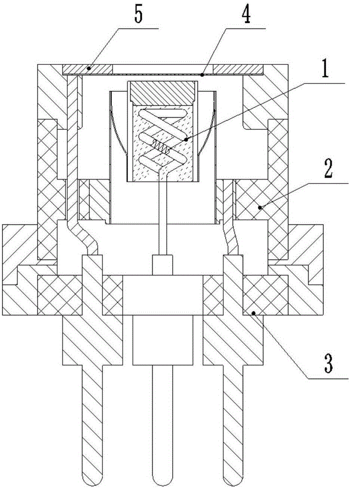
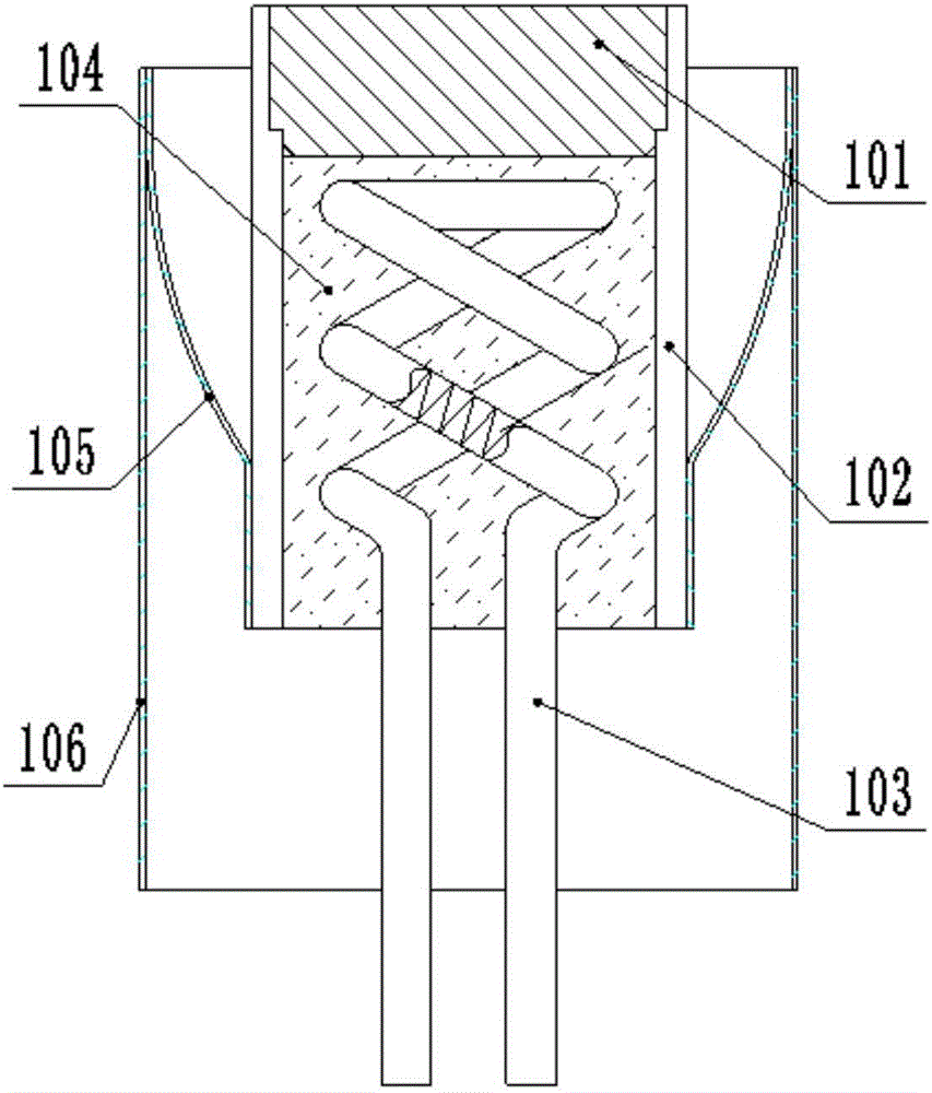
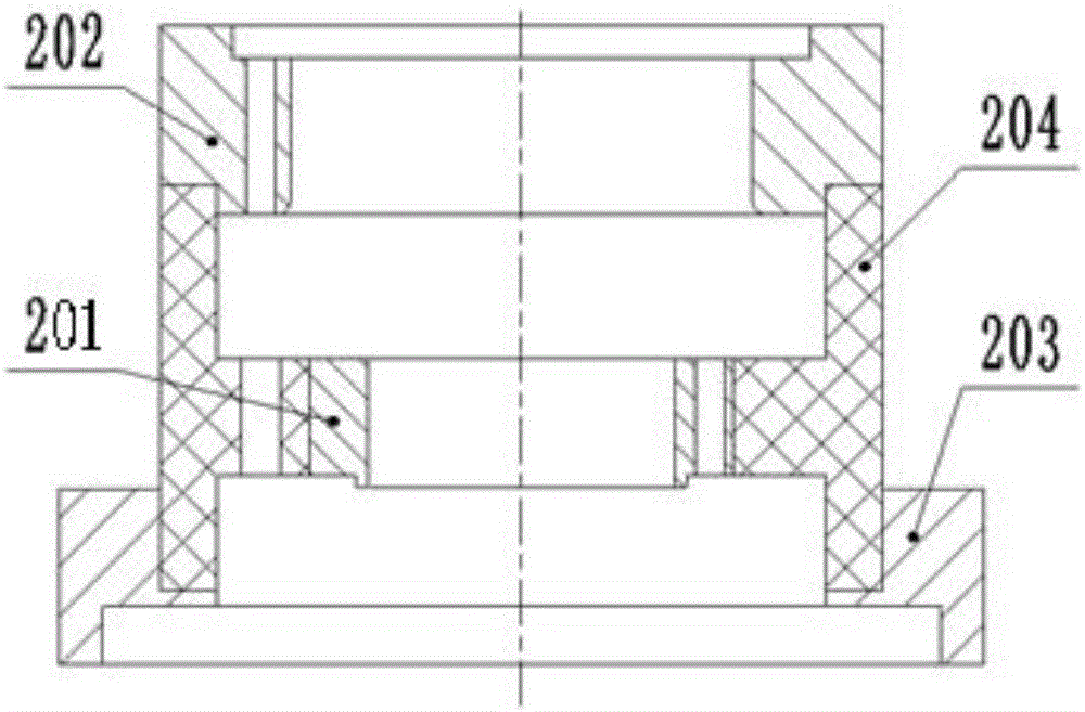
[0025] Such as Figures 1 to 4As shown, an electron gun of the present invention includes a hollow support assembly 2, a cathode assembly 1 is installed in the support assembly 2, and a grid matching the cathode assembly 1 is fixedly installed on the upper end of the support assembly 2 through a grid pressing ring 5. The net 4 also includes a pin assembly 3 connected to the support assembly 2 and the cathode assembly 1, wherein the support assembly 2 includes a cathode assembly support ring 201, a grid support ring 202, a support installation ring 203, a support insulating ceramic cylinder 204, and support installation The ring 203 is used as the base of the supporting assembly, and is used for fixed connection with the pin assembly. The supporting insulating ceramic cylinder 204 provided on the supporting mounting ring 203 is used as the accommodating cavity of the cathode assembly, and is also the mounting frame of the grid supporting ring 202, which is arranged on The catho...
PUM
 Abstract
Description
Claims
Application Information
 - Generate Ideas
- Intellectual Property
- Life Sciences
- Materials
- Tech Scout
- Unparalleled Data Quality
- Higher Quality Content
- 60% Fewer Hallucinations
Browse by: Latest US Patents, China's latest patents, Technical Efficacy Thesaurus, Application Domain, Technology Topic, Popular Technical Reports.
© 2025 PatSnap. All rights reserved.Legal|Privacy policy|Modern Slavery Act Transparency Statement|Sitemap|About US| Contact US: help@patsnap.com