Square workpiece grinding machine

A grinding machine and grinding mechanism technology, applied in grinding machines, manufacturing tools, metal processing equipment, etc., can solve the problems of low grinding efficiency, diffuse dust in machine workshops, and inability to grind square workpieces at the same time, so as to achieve fast grinding speed , the effect of high production efficiency

Active Publication Date: 2017-06-13
CHONGQING TENGTONG IND DESIGN
View PDF10 Cites 16 Cited by
  • Summary
  • Abstract
  • Description
  • Claims
  • Application Information

AI Technical Summary

Problems solved by technology

[0004] The above scheme first clamps the square workpiece with a fixture, and then uses a grinder to grind the end face of the square workpiece. Although this solution solves the problem of potential safety hazards in the prior art when grinding with a manual hand-held grinder, there are still the following problems: 1. This scheme can only polish one surface of a square workpiece at a time, and cannot polish several surfaces of a square workpiece at the same time. After one surface is polished, the fixture needs to be loosened, and the next surface can be polished after turning over the square workpiece. , the grinding efficiency is very low; 2. When this scheme is grinding, the grinding dust that is ground from the square workpiece will fly everywhere, which will cause the dust in the mechanical workshop to diffuse and affect the health of the staff working in the workshop.

Method used


Image

  • Square workpiece grinding machine
  • Square workpiece grinding machine
  • Square workpiece grinding machine

Examples


Embodiment Construction

[0017] The present invention will be described in further detail below by means of specific embodiments:

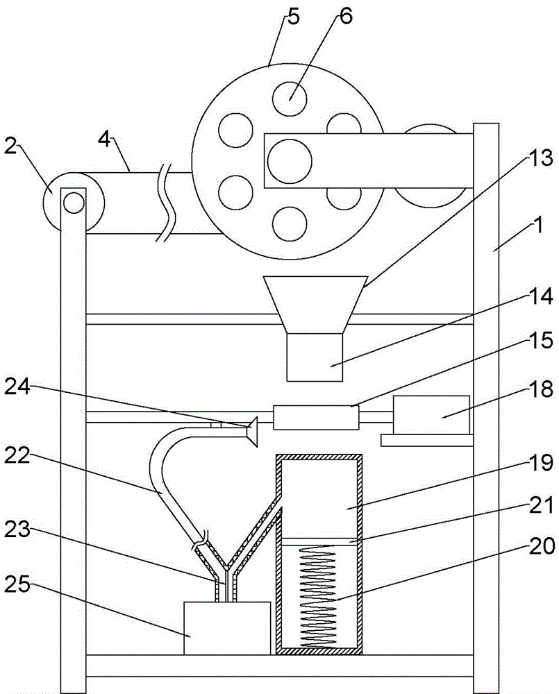
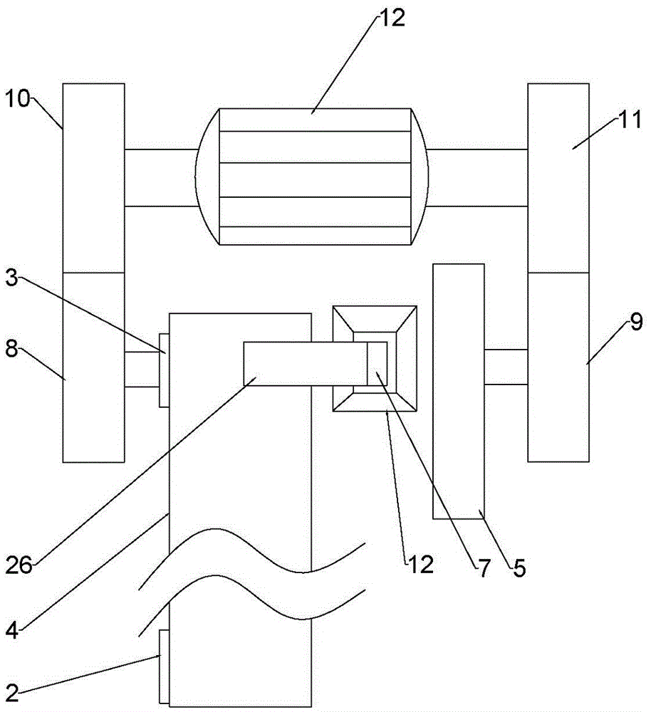
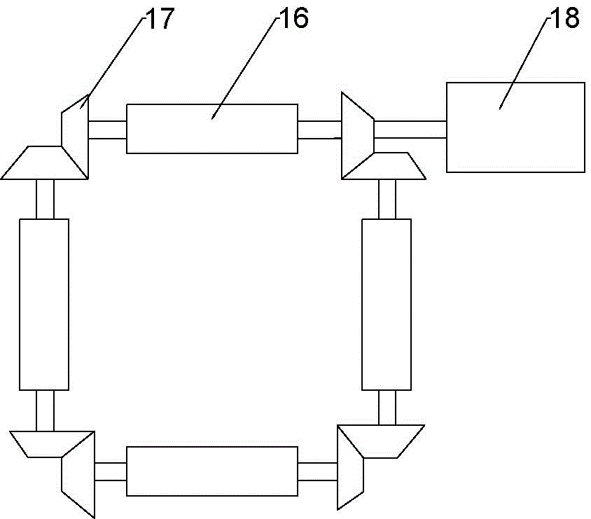
[0018] The reference signs in the drawings of the description include: frame 1, first roller 2, second roller 3, conveyor belt 4, turntable 5, through hole 6, first magnet 7, first gear 8, second gear 9. Third gear 10, fourth gear 11, second motor 12, tapered bucket 13, guide cylinder 14, grinding mechanism 15, grinding roller 16, bevel gear 17, first motor 18, piston cylinder 19, compression spring 20 , the second magnet 21, Y-shaped pipe 22, filter screen 23, conical cover 24, recovery box 25, square workpiece 26.

[0019] Example basic reference figure 1 , figure 2 and image 3 Shown: a square workpiece grinding machine, including a frame 1, a first motor 18, the first motor 18 is connected to the frame 1 by bolts, a conveying mechanism is installed on the frame 1, and the conveying mechanism includes a conveyor belt 4, a first roller Roller 2 and the second rolle...


PUM


Abstract

The invention relates to the field of grinding machines, and discloses a square workpiece grinding machine. The square workpiece grinding machine comprises a rack, a first motor and grinding rollers. The first motor is arranged on the rack, the rack is provided with a conveying mechanism, and a rotary disc is arranged on the part, on one side of the conveying mechanism, of the rack and provided with through holes. First magnets are arranged in the through holes in a sliding manner. A conical hopper is arranged below the part between the conveying belt and the rotary disc. The lower end of the conical hopper is fixedly connected with a guiding barrel. A grinding mechanism is arranged below the grinding barrel. The grinding mechanism comprises the four above grinding rollers. The two ends of each grinding roller are fixedly connected with bevel gears, the bevel gears at the two ends of the grinding rollers are engaged in an end-to-end manner, and the bevel gears are driven by the first motor. A piston barrel is arranged below the grinding mechanism, a second magnet is arranged in the piston barrel in a sliding manner and repels the first magnets, the upper portion of the piston barrel communicates with a suction pipe, and an opening, away from one end of the piston barrel, of the suction pipe faces the grinding mechanism. Compared with the prior art, the periphery of a workpiece can be ground at the same time, and the grinding efficiency is high.

Description

technical field [0001] The invention relates to the field of grinding machines, in particular to a square workpiece grinding machine. Background technique [0002] After the square workpiece is processed, the particles and impurities on the surface need to be removed to obtain a flat surface. Currently, when processing the surface of a square workpiece, the square workpiece is first clamped, and then the hand-held grinder moves back and forth along the square workpiece to grind the surface of the square workpiece. Because the hand needs to hold the grinder for a long time, the hand will be sore, resulting in grinding. The machine falls out of the hand, causing injury to the operator. [0003] For this reason, the patent document whose application number is 201410571435.1 discloses a square workpiece grinding device, which includes a base, a first support base and a second support base arranged on the base, and a clamping bracket is fixed on the first support base. seat, th...

Claims


Application Information

Patent Timeline
Patent Type & Authority Applications(China)
IPC IPC(8): B24B19/00B24B41/00B24B55/06
CPCB24B19/00B24B41/00B24B55/06
Inventor 李庸健
Owner CHONGQING TENGTONG IND DESIGN
Why Eureka
Try Eureka