3D building printing head and mobile 3D building printing device thereof

A printing device and print head technology, which is applied in the direction of manipulators, ceramic molding machines, manufacturing tools, etc., can solve the problems of printing, assembly, transportation and other links, increase production costs and cycles, and complex installation and debugging technology, etc., to shorten production cycle, improve equipment stability, and improve printing efficiency

Active Publication Date: 2017-06-13
中山市新银河传动实业有限公司
View PDF9 Cites 5 Cited by
  • Summary
  • Abstract
  • Description
  • Claims
  • Application Information

AI Technical Summary

Problems solved by technology

It has two production methods. The first method is that the gantry 3D printer is fixedly installed in the factory, firstly prints out the building components, and then transports them to the site to assemble them into buildings. The disadvantage is that there are many links such as printing, assembly, and transportation, which increase the Production cost and cycle
The second method is that the gantry 3D printer is installed, debugged, printed and disassembled on the construction site. The disadvantages are bulky equipment, troublesome transportation, complicated installation and debugging technology, high production cost, and long cycle time.
The disadvantage is that the parallel arm 3D printer needs to be assembled, debugged, printed and disassembled at the construction site. The equipment is heavy, the transportation is troublesome, the installation and debugging technology is complicated, and the production cycle is long. The building to be printed is in the middle of the parallel triangular arm, and the printing space is limited. , the printed building area is small, the vibration of the parallel triangular arm is large, and the printing accuracy is low

Method used


Image

  • 3D building printing head and mobile 3D building printing device thereof
  • 3D building printing head and mobile 3D building printing device thereof
  • 3D building printing head and mobile 3D building printing device thereof

Examples


Embodiment Construction

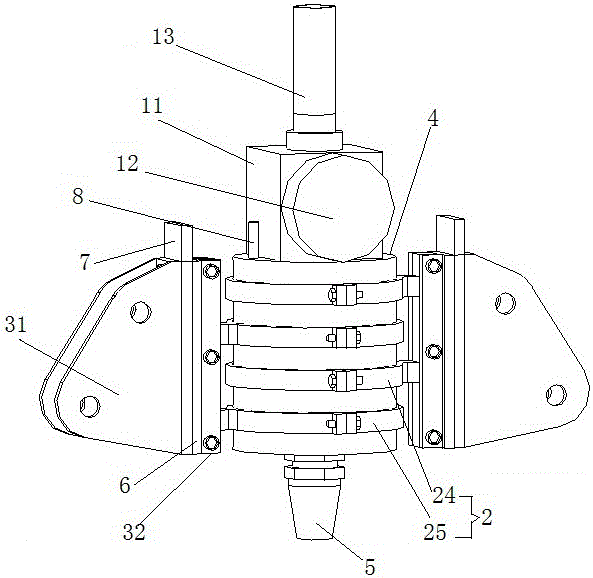
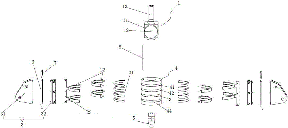
[0035] Such as Figure 1~2 Shown, a kind of 3D construction printing head, comprises hollow printing head body 4, is installed on the top of printing head body 4 and can feed material into the hollow cavity of printing head body 4 feeding device 1, is installed in printing head body 4 the nozzle 5 at the bottom and docked with the hollow cavity of the print head body 4.

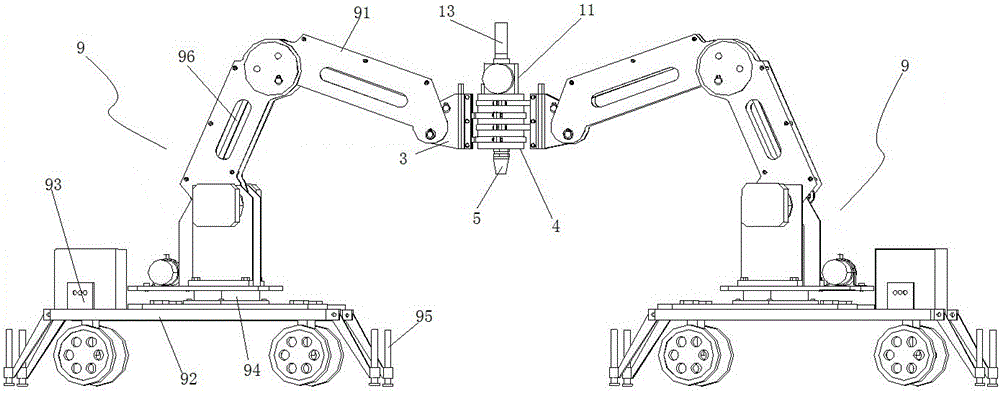
[0036] The outer wall of the print head body 4 is covered with at least two sets of bearing assemblies 2 arranged vertically and staggered. The outer wall of each bearing assembly 2 is correspondingly connected with a printing head connecting frame 3 for connecting with a printing device.

[0037] The bearing assembly 2 includes a bearing 21 and a bearing cap 22 tightly hooped on the bearing 21 , and the bearing cap 22 is fixedly connected to the print head connecting frame 3 through a bearing cap bracket 23 . On the outer wall of the print head body 4 there are grooves for fitting the bearings 21 at interv...


PUM


Abstract

The invention discloses a 3D building printing head. The 3D building printing head comprises a hollow printing head body, a feeding device and a nozzle which is mounted at the bottom of the printing head body and is in butt joint with a hollow cavity of the printing head body. At least two sets of bearing assemblies arranged in an up-and-down staggered manner are mounted on the outer wall of the printing head body in a sleeving manner. The outer wall of each bearing assembly is correspondingly connected with a printing head connecting frame used for being connected with printing equipment. Each printing head connecting frame and the other printing head connecting frame adjacent to the printing head connecting frame can relatively rotate with the printing head body as the axis, and the intersection angle of the two printing head connecting frames can be changed. Meanwhile, the invention provides a mobile 3D building printing device. The 3D building printing head and the mobile 3D building printing device can be conveniently moved to a construction site for directly printing a 3D building, and movement, assembly and debugging are convenient. The loading force and stability of combined mechanical arms are increased, the feed amount is larger, the movement speed is high, the repeated locating precision is high, and the printing speed and printing quality are improved; and the mechanical arms can be longer, and larger buildings can be printed out.

Description

technical field [0001] The invention belongs to the technical field of additive modeling, and in particular relates to a 3D building printing head and a mobile 3D building printing device thereof. Background technique [0002] 3D printing is an additive manufacturing technique that directly forms a final product by stacking materials. [0003] At present, the known 3D construction printers are composed of a printer body, a printing head, a 3D motion mechanism, a feeding device, a workbench, a control system, auxiliary machinery, electrical devices, and the like. It is mainly divided into the following structural forms: [0004] 1. Gantry frame structure: Arranged with 2-4 columns, the x and y axes are installed horizontally, the printing head is installed on the x axis, the columns are used as the z axis, and the printing head moves in 3D space to print out building components. It has two production methods. The first method is that the gantry 3D printer is fixedly install...

Claims


Application Information

Patent Timeline
Patent Type & Authority Applications(China)
IPC IPC(8): B28B1/00B33Y30/00
CPCB28B1/001B33Y30/00B25J5/007B25J9/009
Inventor 张鸿斌
Owner 中山市新银河传动实业有限公司
Why Eureka
Try Eureka