
Film blowing equipment

A technology of equipment and film cylinder, applied in the field of film blowing equipment, can solve problems such as film damage

Active Publication Date: 2017-06-13
瑞安市铭德机械有限公司
View PDF21 Cites 2 Cited by
  • Summary
  • Abstract
  • Description
  • Claims
  • Application Information

AI Technical Summary

Problems solved by technology

[0005] However, if there is an adhesive on the film, it will be bonded to the roller, and a large amount of film will accumulate at the roller, and the roller will still rotate at this time, which will cause damage to the film

Method used


Image

  • Film blowing equipment
  • Film blowing equipment
  • Film blowing equipment

Examples


Embodiment Construction

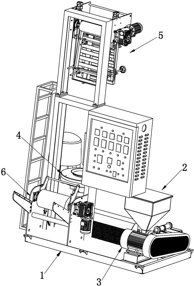
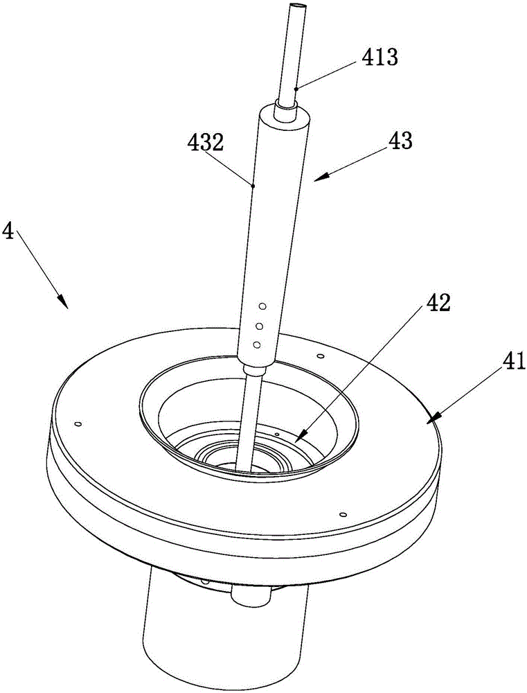
[0026] like figure 1 — Figure 8 The blown film equipment shown includes an organism 1, a plastic particle feeding hopper 2 arranged on the body 1, a plastic particle heating and melting device 3 connected with the plastic particle feeding hopper 2, and a blowing device connected with the plastic particle heating and melting device 3. The film device 4, the stretching finishing device 5 connected with the blown film device 4 and the winding device 6 connected with the stretching finishing device 5, the blown film device 4 includes a blown film cylinder 41 and a mold located in the blown film cylinder 41 42. The film blowing cylinder 41 is provided with a mold rod 43 extending to the outside. The mold rod 43 includes a rod body 431 connected to the blowing mold cylinder 41 and a guide sleeve 432 sleeved outside the rod body 431. The stretching finishing device 5 includes Support 51, some adjustable roller shafts erected on the support 51, the rod body 431 is a hollow rod body,...


PUM


Abstract

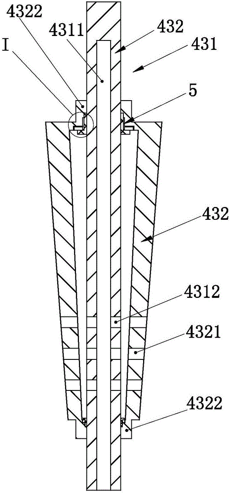
The invention relates to film machining equipment, in particular to film blowing equipment. According to the technical scheme, the film blowing equipment comprises a machine body, a plastic particle charging hopper arranged on the machine body, a plastic particle heating melting device, a film blowing device, a stretching tidying device and a rolling device. The film blowing device comprises a film blowing barrel and a die. A die rod extending to the outside is arranged in the film blowing barrel and comprises a rod body connected with the film blowing barrel, and a guiding sleeve. The stretching tidying device comprises a support and a plurality of adjustable roll shafts erected on the support. The rod body is a hollow rod body and is internally provided with an air way. The rod body is provided with a plurality of air holes communicating with the inner air way of the rod body. Communicating through holes corresponding to the positions of the air holes are formed in the lower portion of the guiding sleeve, and a sealing assembly is arranged between each of the two axial ends of the guiding sleeve and the rod body. By the adoption of the above technical scheme, the film blowing equipment preventing bonding of a film and the roll shafts, preventing film damage, making film guidance stable and improving the machining quality is provided.

Description

technical field [0001] The invention relates to a film processing equipment, in particular to a film blowing equipment. Background technique [0002] The film blowing machine is a processing equipment that heats and melts plastic particles, and then blows them into films. The traditional film blowing machine is mainly composed of a body, a plastic particle feeding hopper on the body, a plastic particle heating and melting device connected with the plastic particle feeding hopper, a film blowing device connected with the plastic particle heating and melting device, and a film blowing device. A stretching finishing device and a winding device connected with the stretching finishing device. [0003] The traditional blown film device mainly consists of a blown film cylinder and a mold inside the blown film cylinder. The blown film cylinder is equipped with a mold rod extending to the outside. The mold rod is mainly used to accumulate the blown film to achieve lamination. and o...

Claims


Application Information

Patent Timeline
IPC IPC(8): B29C55/28
CPCB29C55/28
Inventor 林安国方文龙
Owner 瑞安市铭德机械有限公司
Learn More