

Light source component and 3D (three-dimensional) printer
A light source component and component technology, applied in 3D object support structures, metal processing equipment, manufacturing tools, etc., can solve problems that affect the life of LCD and LED, LCD is not resistant to high temperature, large heat generation, etc., to achieve good heat dissipation and cooling effect , small volume, long service life
- Summary
- Abstract
- Description
- Claims
- Application Information
AI Technical Summary
Problems solved by technology
Method used
Image

Examples
no. 1 example
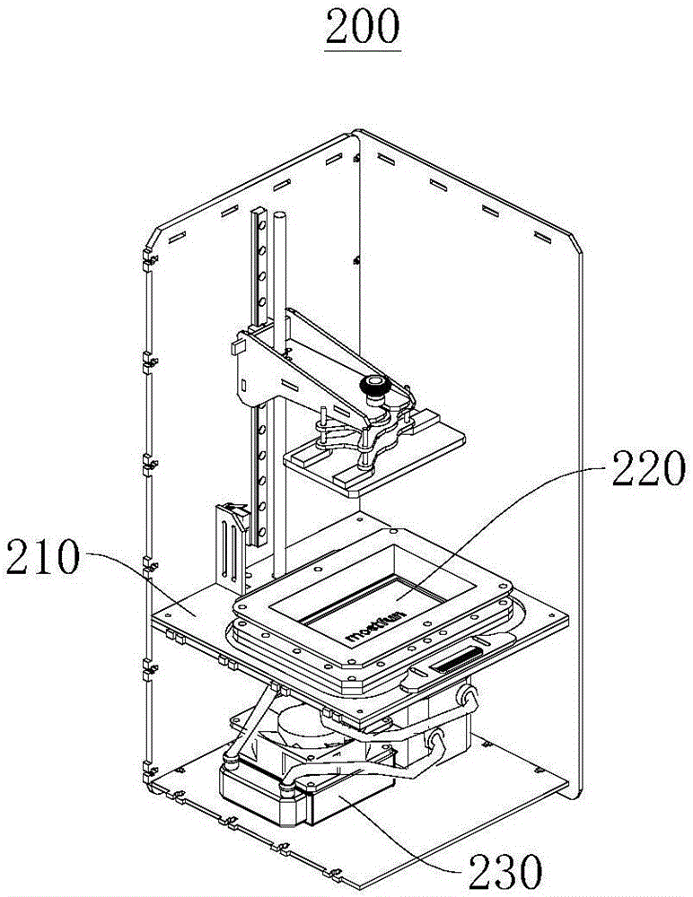
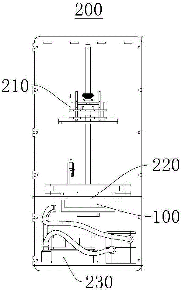
[0040] This embodiment provides a 3D printer 200, the 3D printer 200 includes a printer body 210, and an LCD screen 220, a heat sink 230, a light source assembly 100 and the like arranged in the printer body 210. Due to the use of the light source assembly 100, the internal structure of the 3D printer 200 is compact, and the overall volume is small, and when in use, the heat sink 230 ensures the fluid circulation in the light source assembly 100 to take away the heat generated by the light source substrate 110 for heat dissipation and cooling. Good effect and long service life. It should be noted that, in other preferred embodiments, the light source assembly 100 provided in this embodiment can also be applied to other scenarios, such as machine vision and the like.
[0041] figure 1 A schematic diagram of the structure of the 3D printer 200 in the first viewing angle provided in this embodiment. figure 2 A schematic structural diagram of the second viewing angle of the 3D pr...
no. 2 example
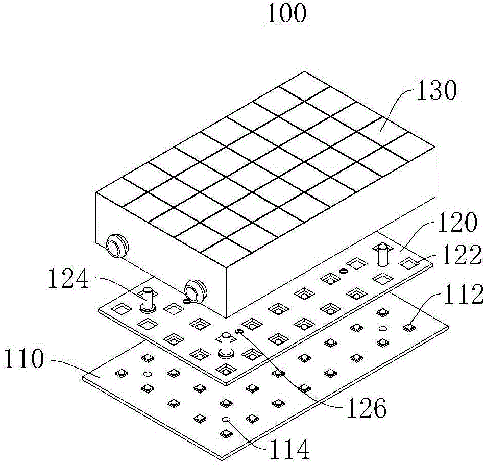
[0065] Figure 6 A schematic diagram of an exploded structure of the light source assembly 300 provided in this embodiment. Please refer to Figure 6 , The light source assembly 300 provided in this embodiment includes a light source substrate 310 , a bottom plate 320 , a heat dissipation top plate 340 and a reflective assembly 330 . The light source substrate 310 is connected to the bottom plate 320 , the bottom plate 320 is connected to one side of the reflective assembly 330 , and the heat dissipation top plate 340 is connected to the side of the reflective assembly 330 away from the bottom plate 320 .
[0066] Figure 7 A schematic cross-sectional structure diagram of the light source assembly 300 provided in this embodiment. Figure 8 A structural schematic diagram of a viewing angle of the reflective assembly 330 of the light source assembly 300 provided for the embodiment. Please refer to Figure 7 and Figure 8 , preferably, in this embodiment, the reflective ass...
PUM
 Abstract
Description
Claims
Application Information