Unloading device for non-tipping flatbed vehicles
What is Al technical title?
Al technical title is built by PatSnap Al team. It summarizes the technical point description of the patent document.
A technology of unloading device and automobile, which is applied in the direction of freight vehicles, loading and unloading vehicle arrangements, motor vehicles, etc. It can solve the problems of insufficient length of excavator arms, time-consuming and laborious unloading of goods, etc., so as to reduce loss, The effect of increasing the unloading speed and improving the unloading efficiency
Active Publication Date: 2018-11-13
合山锌业科技有限公司
View PDF13 Cites 0 Cited by
Summary
Abstract
Description
Claims
Application Information
AI Technical Summary
This helps you quickly interpret patents by identifying the three key elements:
Problems solved by technology
Method used
Benefits of technology
Problems solved by technology
[0002] Existing cargo flatbed trucks are self-unloading, which can automatically tilt the container for unloading, but at present, more non-dumping flatbed trucks are still unloading mainly by manpower, and some rely on excavators for unloading. However, the arm of the excavator is not long enough to reach the top of the flatbed truck container, and auxiliary manpower is still required for unloading, especially for materials such as coal and other bulk and granular blends, manpower unloading seems time-consuming and laborious, but only Even if the arm of the excavator is lengthened, the cargo cannot be unloaded cleanly at one time
Method used
Image
Click on the blue label to locate the original text in one second.
Reading with bidirectional positioning of images and text.
Examples
Embodiment Construction
[0032] The present invention will be further described in detail below in conjunction with the accompanying drawings, so that those skilled in the art can implement it with reference to the description.
[0033] It should be noted that the experimental methods described in the following embodiments, unless otherwise specified, are conventional methods, and the reagents and materials, if not otherwise specified, can be obtained from commercial sources; in the description of the present invention, The terms "landscape", "portrait", "top", "bottom", "front", "rear", "left", "right", "vertical", "horizontal", "top", "bottom", The orientation or positional relationship indicated by "inner", "outer", etc. is based on the orientation or positional relationship shown in the drawings, which is only for the convenience of describing the present invention and simplifying the description, and does not indicate or imply that the referred device or element must have Certain orientations, co...
PUM
Abstract
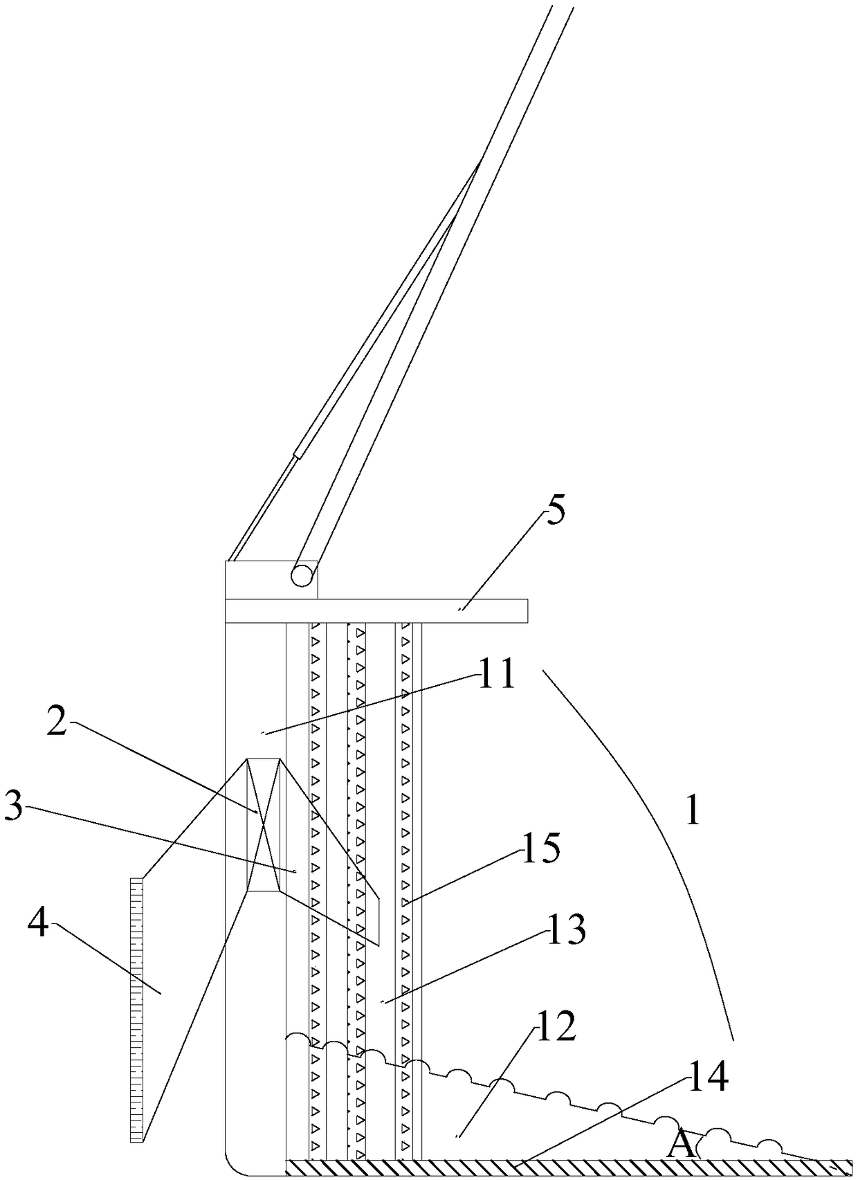
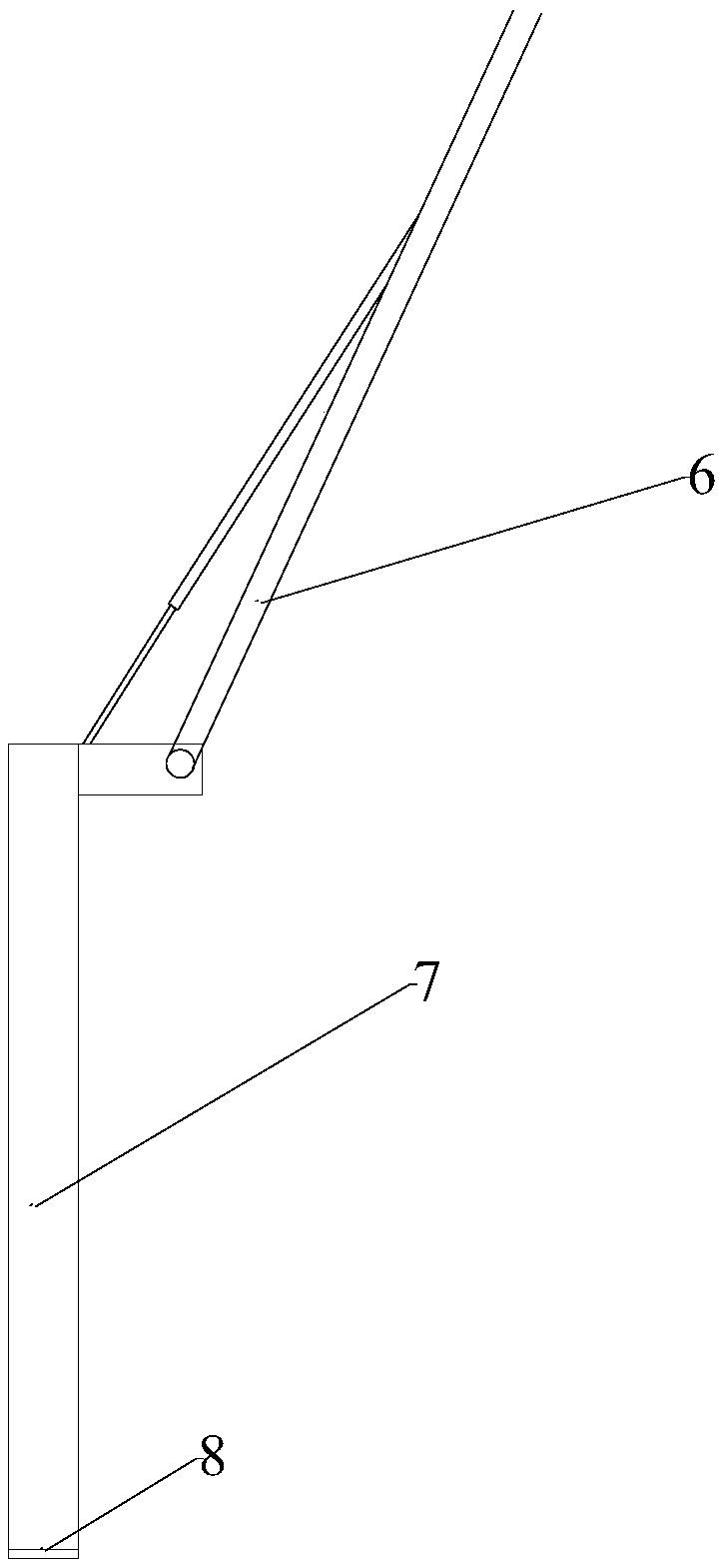
The invention discloses a dumping device applicable to a non-self-dumping flat truck. The dumping device comprises a truck body, a cab and a first movable arm, wherein the first movable arm is connected with a first dumping rake, the first dumping rake comprises a dumping bucket, the dumping bucket comprises a material blocking box plate, a material scraping plate, two lateral plates, a first brush, a second brush, an exhaust fan, a material-guide flat mouth, a material-sucking flat mouth and a dustproof plate, the slope of the material scraping plate is upwardly arranged to allow the material scraping plate and the material blocking box plate to form an L shape, the two lateral plates are respectively arranged on the left and right sides of the material scraping plate, the first brush comprises first brush bodies respectively arranged on the left and right sides of the material scraping plate, the second brush comprises brush layers respectively arranged on the outer sides of the two lateral plates, the exhaust fan is arranged in the cylindrical cavity of the material blocking box plate and electrically connected with a fan switch, the material-guide flat mouth is arranged on one side, with the material scraping plate, of the material blocking box plate, one end of the material-guide flat mouth is communicated with a material guide port, the material-sucking flat mouth is arranged on the other side of the material blocking box plate, one end of the material-sucking flat mouth is communicated with a material sucking port, and the dustproof plate is arranged at the top of the material blocking box plate. The dumping device is simple in structure, easy to operate and clean in dumping.
Description
technical field [0001] The invention relates to the technical field of unloading equipment. More specifically, the present invention relates to a discharge device suitable for non-dump flatbed vehicles. Background technique [0002] Existing cargo flatbed trucks are self-unloading, which can automatically tilt the container for unloading, but at present, more non-dumping flatbed trucks are still unloading mainly by manpower, and some rely on excavators for unloading. However, the arm of the excavator is not long enough to reach the top of the flatbed truck container, and auxiliary manpower is still required for unloading, especially for materials such as coal and other bulk and granular blends, manpower unloading seems time-consuming and laborious, but only Even if the arm of the excavator is lengthened, the cargo cannot be unloaded cleanly at one time. Contents of the invention [0003] It is an object of the present invention to solve at least the above-mentioned probl...
Claims
Application Information
Patent Timeline
Application Date:The date an application was filed.
Publication Date:The date a patent or application was officially published.
First Publication Date:The earliest publication date of a patent with the same application number.
Issue Date:Publication date of the patent grant document.
PCT Entry Date:The Entry date of PCT National Phase.
Estimated Expiry Date:The statutory expiry date of a patent right according to the Patent Law, and it is the longest term of protection that the patent right can achieve without the termination of the patent right due to other reasons(Term extension factor has been taken into account ).
Invalid Date:Actual expiry date is based on effective date or publication date of legal transaction data of invalid patent.