Eureka AIR delivers breakthrough ideas for toughest innovation challenges, trusted by R&D personnel around the world.

Braking dual-cavity auxiliary master cylinder dual-motor wire-controlled hydraulic braking system

A brake master cylinder and hydraulic brake technology, which is applied in the direction of brake transmission, brake, transportation and packaging, etc., can solve the problems of large volume, high price and high motor requirements of the vacuum booster, and achieve simple and convenient layout and high rigidity The effect of reducing the strength requirement and reducing the volume

Active Publication Date: 2017-12-19
JILIN UNIV
View PDF8 Cites 0 Cited by
  • Summary
  • Abstract
  • Description
  • Claims
  • Application Information

AI Technical Summary

Problems solved by technology

[0006] The technical problem to be solved by the present invention is to overcome the large volume and high price of the vacuum booster in the traditional braking system, and the high requirements on the motor, the high price and the high price caused by the motor-assisted wire-controlled hydraulic braking system requiring the motor to quickly switch between forward and reverse. To solve the problem of rapid pressure build-up and precise pressure control, a brake dual-chamber sub-master cylinder dual-motor wire-controlled hydraulic brake system is provided

Method used


Image

  • Braking dual-cavity auxiliary master cylinder dual-motor wire-controlled hydraulic braking system
  • Braking dual-cavity auxiliary master cylinder dual-motor wire-controlled hydraulic braking system
  • Braking dual-cavity auxiliary master cylinder dual-motor wire-controlled hydraulic braking system

Examples


Embodiment Construction

[0055] The present invention is described in detail below in conjunction with accompanying drawing:

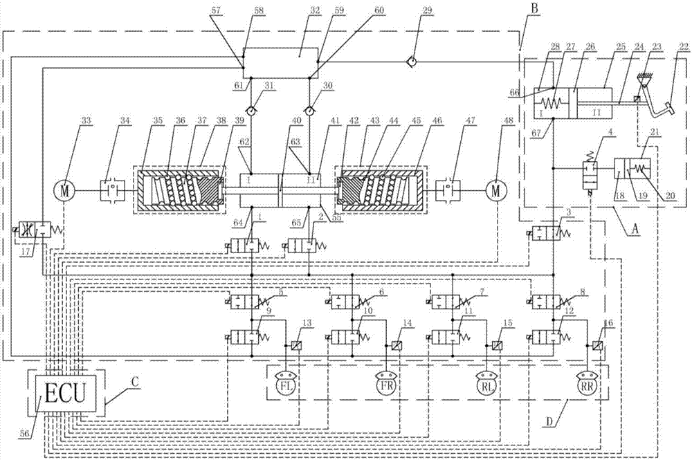
[0056] Brake dual-chamber sub-master cylinder dual-motor wire-controlled hydraulic brake system includes brake master cylinder output unit A, hydraulic control unit (HCU) B, electronic control unit (ECU) C and wheel brake D

[0057] The brake master cylinder output unit A includes a brake pedal 22, a pedal displacement sensor 23, a brake master cylinder 28, a pedal feeling simulator 18, and a fourth switch solenoid valve 4; wherein:

[0058] The pedal feel simulator 18 includes a pedal feel simulator piston 19 , a pedal feel simulator spring 20 , and a pedal feel simulator case 21 .

[0059] The brake master cylinder 28 includes a master cylinder housing 25 , a master cylinder piston 26 , a master cylinder I cavity return spring 27 , a master cylinder piston 26 and a push rod 24 .

[0060] The master cylinder piston 26 is installed in the master cylinder housing 25, the master ...


PUM


Abstract

The invention discloses a hydraulic brake-by-wire system with braking two-cavity pair master cylinder and two motors, aimed at overcoming the problems of high requirement for motors, high prices, and fast pressure buildup and accurate pressure control due to a hydraulic brake-by-wire system, which is large in size, expensive, and powered by a motor, of a vacuum booster of a traditional brake system requesting rapid positive and negative rotation switching of the motor. The system comprises a braking master cylinder output unit, a hydraulic control unit, an electronic control unit, and wheel brakes. The hydraulic control unit comprises a third on-off solenoid valve, ninth to twelfth on-off solenoid valves, and an oil cup. The braking master cylinder output unit is connected to the hydraulic control unit using a pipe by means of the braking master cylinder and the oil cup therein. Additionally, the braking master cylinder output unit is connected to the hydraulic control unit using a pipe by means of the braking master cylinder, the third on-off solenoid valve and the hydraulic control unit. The ninth to twelfth on-off solenoid valves are connected to four of the wheel brakes in order using pipes. The electronic control unit is connected to the braking master cylinder output unit and the hydraulic control unit by wires.

Description

technical field [0001] The invention relates to a braking system belonging to the technical field of automobile braking systems. More precisely, the present invention relates to a dual-chamber auxiliary master cylinder dual-motor wire-controlled hydraulic braking system. Background technique [0002] With the rapid development of today's automobile industry, people's demand for new high-performance automobile braking systems is gradually increasing. The braking system of traditional cars uses a vacuum booster, which has the disadvantages of large volume, complex structure, high dependence on the engine, and inaccurate brake pressure control. At present, most cars have canceled the use of vacuum booster systems. In order to meet today's demand for high-performance brake systems and the research and development needs of the emerging electric vehicle industry, people have gradually begun to research and explore brake-by-wire systems. [0003] Existing brake-by-wire systems ar...

Claims


Application Information

Patent Timeline
Patent Type & Authority Patents(China)
IPC IPC(8): B60T13/14B60T13/68B60T13/74
CPCB60T13/142B60T13/68B60T13/745
Inventor 李静王晨刘鹏夏承贺孙禄
Owner JILIN UNIV
Why Eureka
Eureka Blog
Learn More