
Washing, dehydration and drying continuous processing process

A processing technology, continuous technology, applied in the direction of liquid/gas/steam removal by centrifugal force, equipment configuration for processing textile materials, etc., can solve problems such as uneven dehydration of inner and outer layers, waste of manpower, and inability to realize continuous production

Active Publication Date: 2017-06-13
绍兴国周针织科技有限公司
View PDF7 Cites 1 Cited by
  • Summary
  • Abstract
  • Description
  • Claims
  • Application Information

AI Technical Summary

Problems solved by technology

The conventional centrifugal dehydrator removes water through the centrifugal force generated by high-speed operation. Although this method is convenient to operate, during the operation process, since the loose fibers are all squeezed in the cylinder of the dehydrator in a piled state, the inner layer and the outer layer Due to the difference in centrifugal force between the layers, it will cause uneven dehydration of the inner and outer layers; at the same time, it is necessary to manually load and remove the fibers, which is a waste of manpower, and this centrifuge is produced intermittently. The fiber needs to be transferred to the dehydrator. After being dehydrated by the dehydrator, it is transferred out and sent to the oven. The whole process is divided into three discontinuous steps, which can neither achieve continuous production nor guarantee the dehydration effect of the fiber.

Method used


Image

  • Washing, dehydration and drying continuous processing process
  • Washing, dehydration and drying continuous processing process
  • Washing, dehydration and drying continuous processing process

Examples


Embodiment 1

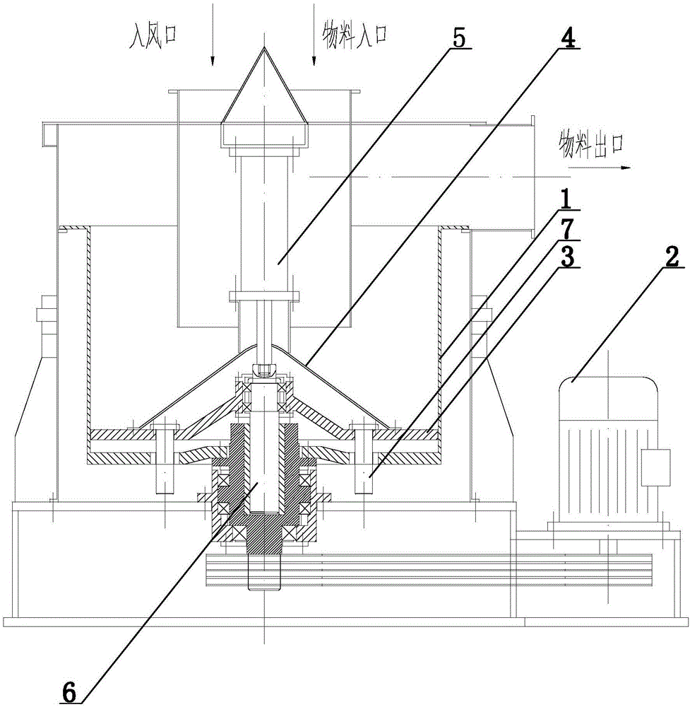
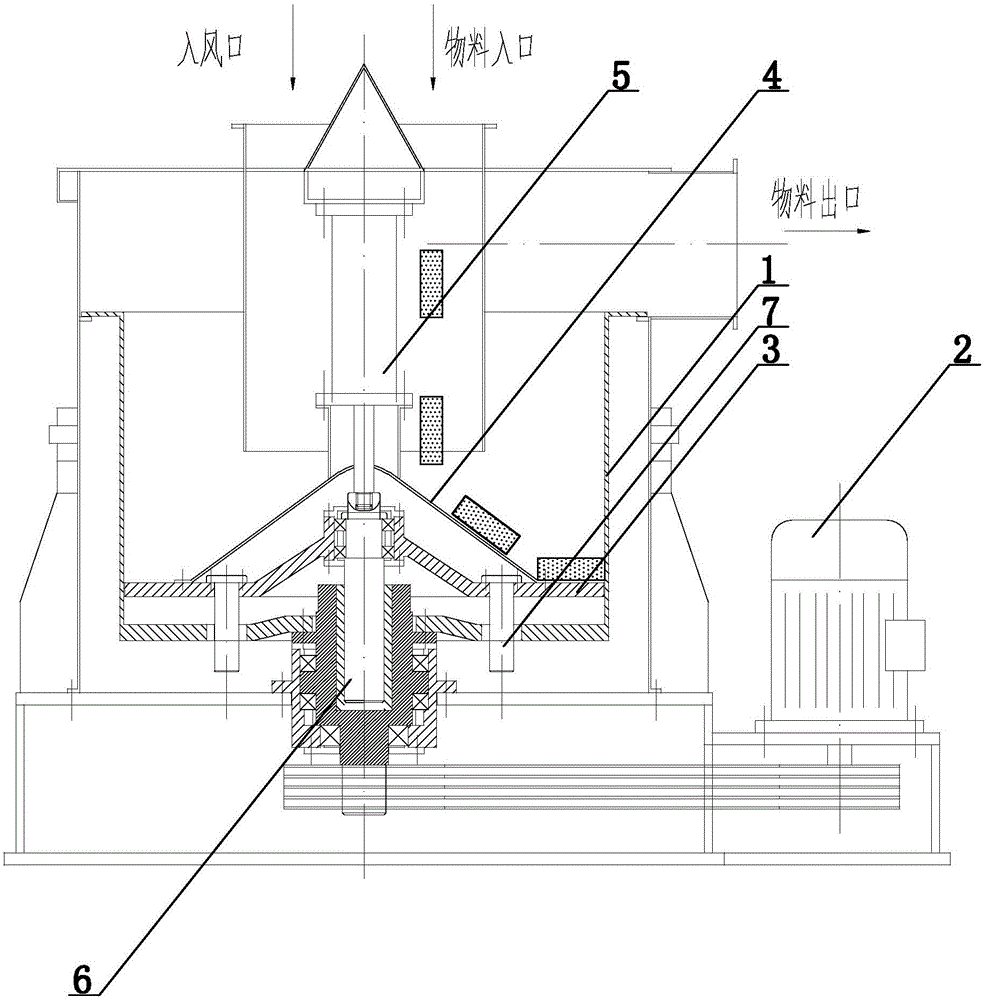
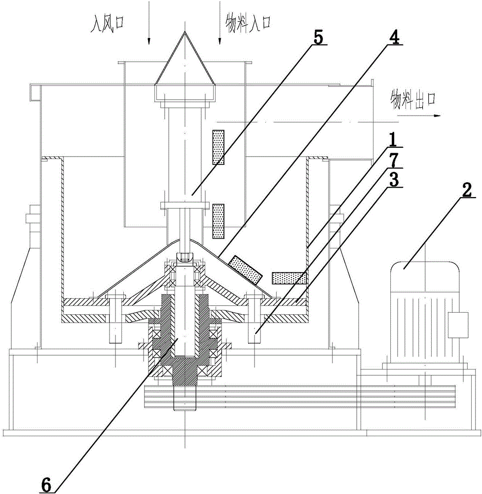
[0024] In this embodiment, the elution drying continuous processing technology combines figure 1 , including the cleaning process, dehydration process and drying process carried out in sequence. After the materials to be processed are cleaned by the cleaning process, they are sent to the dehydration process. The dehydration process is completed in the dehydration mechanism. The dehydration mechanism includes a drum 1, a material inlet , material outlet, motor 2, pallet 3, hydraulic cylinder or cylinder 5, lifting shaft 6, guide rod 7, drum 1 is driven by motor 2; pallet 3 is slidably installed in drum 1 through guide rod 7, hydraulic cylinder Or the cylinder 5 is located above the supporting plate, and the supporting plate 3 is connected with the hydraulic cylinder or cylinder 5 through the lifting shaft 6. Under the pull of the hydraulic cylinder or cylinder 5, the guide rod 7 is used as the track to reciprocate up and down relative to the drum 1. The cleaned material enters ...

Embodiment 2

[0028] The setting and working principle of this embodiment are the same as those of Embodiment 1, the difference is that: the supporting plate 3 is provided with a cover 4, and the cover 4 is located below the material inlet. When the cover 4 is set as a structure with a high center (that is, below the material inlet, preferably directly below the material inlet) and low sides, the material falls on the cover 4 and, under its own inertial force and gravity, moves along the middle The slopes on both sides automatically slide down to both sides, effectively preventing materials from accumulating below the material inlet.

Embodiment 3

[0030] The setting and working principle of this embodiment are the same as those of Embodiment 1, the difference is that the drum 1 is driven by a motor to rotate, and is driven to reciprocate up and down by hydraulic pressure or air pressure, and the supporting plate 3 only changes its position as the drum 1 rotates. Invariably, when the drum 1 moves downward along the guide rod 7 relative to the supporting plate 3 , the material gradually moves upward until it enters the material outlet.


PUM


Abstract

The invention relates to a washing, dehydration and drying continuous processing process, and belongs to the technical field of fiber treatment. The process comprises a cleaning procedure, a dehydration procedure and a drying procedure which are set in sequence, and fibers to be treated are cleaned through the cleaning procedure and then fed into the dehydration procedure; the dehydration procedure is completed in a dehydration mechanism, and the dehydration mechanism comprises a rotary barrel, a material inlet, a supporting plate and a material outlet. The rotary barrel is driven by a motor, and the supporting plate is mounted in the rotary barrel in a sliding mode. The cleaned materials enter the rotary barrel through the material inlet, after the cleaned materials fall onto the supporting plate, the motor drives the rotary barrel and the supporting plate to rotate together, meanwhile, the supporting plate and the rotary barrel do vertical reciprocating motion, the materials are moved upwards, and after dehydration is completed in the moving process, the materials are conveyed into a drying mechanism through the material outlet to be dried. The process is applied to fiber cleaning treatment, and has the advantages of being fast in dehydration, even in drying, low in energy consumption, low in cost, capable of achieving continuous operation and the like.

Description

technical field [0001] The invention relates to a continuous elution-drying processing technology, which belongs to the technical field of fiber processing. Background technique [0002] Dehydration is a necessary process in the processing of bulk fibers. The conventional centrifugal dehydrator removes water through the centrifugal force generated by high-speed operation. Although this method is convenient to operate, during the operation process, since the loose fibers are all squeezed in the cylinder of the dehydrator in a piled state, the inner layer and the outer layer Due to the difference in centrifugal force between the layers, it will cause uneven dehydration of the inner and outer layers; at the same time, it is necessary to manually load and remove the fibers, which is a waste of manpower, and this centrifuge is produced intermittently. The fiber needs to be transferred to the dehydrator. After being dehydrated by the dehydrator, it is transferred out and sent to ...

Claims


Application Information

Patent Timeline
IPC IPC(8): D06B15/10D06B23/20
CPCD06B15/10D06B23/20
Inventor 金国周俞月根何林伟俞诚
Owner 绍兴国周针织科技有限公司
Learn More