Gangway structure for connecting floating bridge with floating platform

A floating platform and pontoon technology, which is applied in the direction of construction, can solve the problems of increasing the difficulty of connecting the pontoon and the floating platform, the excessive height difference between the floating platform and the pontoon, and the difficulty of transporting materials at sea, so as to ensure the strength and draught difference Large, easy-to-install effect

Active Publication Date: 2017-06-13
708TH RES INST OF CSSC
View PDF4 Cites 4 Cited by
  • Summary
  • Abstract
  • Description
  • Claims
  • Application Information

AI Technical Summary

Problems solved by technology

[0004] However, due to the height difference between the floating platform and the pontoon and its constant change with the draft of the platform, the relative movement between the platform and the pontoon under the ocean wave environment and its load, etc., have increased the difficulty of connecting the pontoon and the floating platform. As a result, the connection springboard structure of the existing pontoon bridge cannot be used for the connection between buoys with large draft changes, large relative motion ranges, and bad sea conditions, which has caused certain difficulties for marine material transportation, and there is no safety limit setting. When the difference is too large, the connection structure will be damaged, and the height difference between the floating platform and the pontoon bridge will be too large, which will affect the traffic of vehicles
[0005] To sum up, the existing connection structure between the floating bridge and the floating platform has the problems of poor adaptability and lack of safety limit

Method used


Image

  • Gangway structure for connecting floating bridge with floating platform
  • Gangway structure for connecting floating bridge with floating platform
  • Gangway structure for connecting floating bridge with floating platform

Examples


Embodiment Construction

[0034] In order to make it easy to understand the technical means, creative features, goals and effects achieved by the present invention, the following examples are combined with the appended figure 1 to attach Figure 11 The technical solutions provided by the present invention are described in detail, but the following content is not intended as a limitation of the present invention.

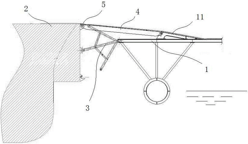
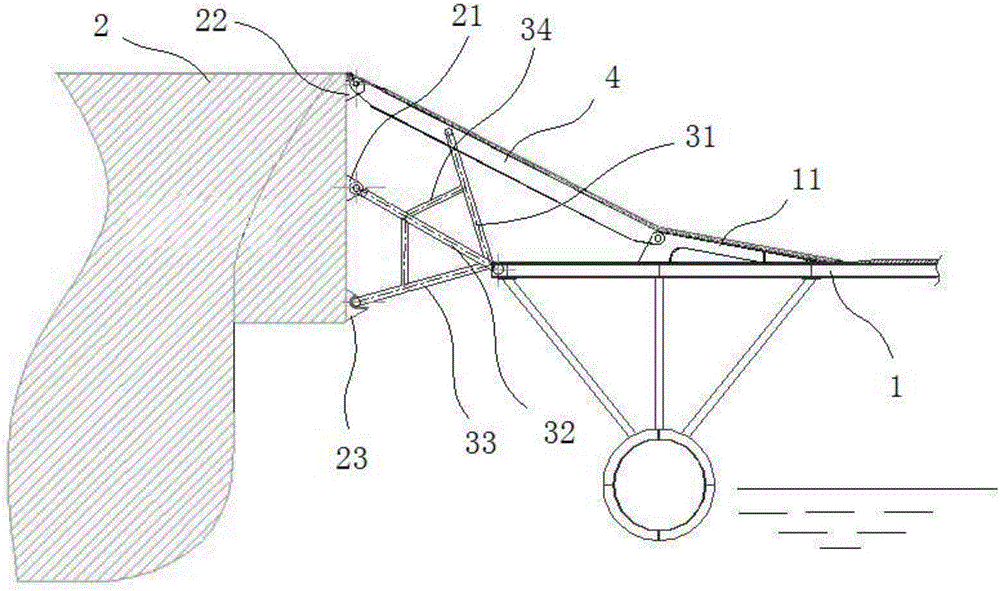
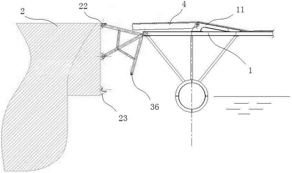
[0035] figure 1 It is a structural diagram of an embodiment of a springboard structure connecting a pontoon bridge and a floating platform according to the present invention; figure 2It is a structural diagram of the minimum draft state in a preferred embodiment of the present invention; image 3 It is a structural diagram at the maximum draft state in a preferred embodiment of the present invention. Such as figure 1 , figure 2 as well as image 3 As shown, the springboard structure connecting the pontoon bridge and the floating platform provided in this embodiment includes: pontoon b...


PUM


Abstract

The invention provides a gangway structure for connecting a floating bridge with a floating platform and belongs to the technical field of floating bridge connection. The gangway structure for connecting the floating bridge with the floating platform comprises the floating bridge, the floating platform, footplates, a gangway and supporting limiting frames, wherein the footplates are arranged on the floating bridge and the floating platform; the gangway is hinged between the footplates of the floating platform and the floating bridge; and the supporting limiting frames are hinged on the floating bridge and the floating platform. According to the gangway structure for connecting the floating bridge with the floating platform, as a platform footplate is hinged on a floating bridge platform and the platform footplate is matched with a truss type gangway, the adapted draft difference is great and the adaptation is high; as the supporting limiting frames are arranged and a main support is arranged in the form of a double A-shaped truss, the position of the gangway structure between the floating platform and the floating bridge is effectively limited at a maximum draft difference and at a minimum draft difference so as to ensure that vehicles can safely pass; damage of the bridge body caused by collision between the floating bridge and the floating platform can be avoided; and moreover, the design load of the truss type gangway is reduced, the weight of the structure is reduced and the safety is enhanced.

Description

technical field [0001] The invention relates to the technical field of floating bridge connection, in particular to a springboard structure connecting a floating bridge and a floating platform. Background technique [0002] As one of the main tools for crossing ravines, bridges have a long history of construction, play a pivotal role in people's production and life, and become a necessary carrier tool in life. [0003] At present, the existing bridges include reinforced concrete bridges and steel structure floating bridges. Reinforced concrete bridges are durable and have low maintenance costs. The construction period is short, and it can be recycled and used with stronger adaptability. It is generally arranged in places with large environmental changes and instability, such as the sea. In the sea with strong wind and waves, due to the deep water depth and long distance, the cost of building a reinforced concrete bridge is not only high, but also there is a risk of damage, ...

Claims


Application Information

Patent Timeline
Patent Type & Authority Applications(China)
IPC IPC(8): E01D15/24
CPCE01D15/24
Inventor 张延昌魏跃峰羊卫王醍朱耀胜姜志宇
Owner 708TH RES INST OF CSSC
Why Eureka
Try Eureka