Electrical isolation prestressed anchorage system and construction and installation method thereof

An installation method and electrical isolation technology, applied in the direction of erecting/assembling bridges, structural elements, bridges, etc., can solve the problems of poor airtightness of anchoring units, inability to detect prestressed anti-corrosion performance, and inability to better achieve electrical isolation performance, etc., to achieve Simple installation and construction, good anti-corrosion performance

Active Publication Date: 2017-06-13
LIUZHOU OVM MASCH CO LTD
View PDF5 Cites 5 Cited by
  • Summary
  • Abstract
  • Description
  • Claims
  • Application Information

AI Technical Summary

Problems solved by technology

[0003] For anti-corrosion protection of prestressed structures, it is necessary to isolate the prestressed tendons from the external environment to form an internal airtight structure to prevent the external environment from electrochemically corroding the prestressed tendons; and the usual anti-corrosion methods mostly use plastic bellows and plastic The form of the anchor cover body forms an anchor unit with poor airtightness, which cann...

Method used


Image

  • Electrical isolation prestressed anchorage system and construction and installation method thereof
  • Electrical isolation prestressed anchorage system and construction and installation method thereof
  • Electrical isolation prestressed anchorage system and construction and installation method thereof

Examples


Embodiment 1

[0051] An electrically isolated prestressed anchorage system,

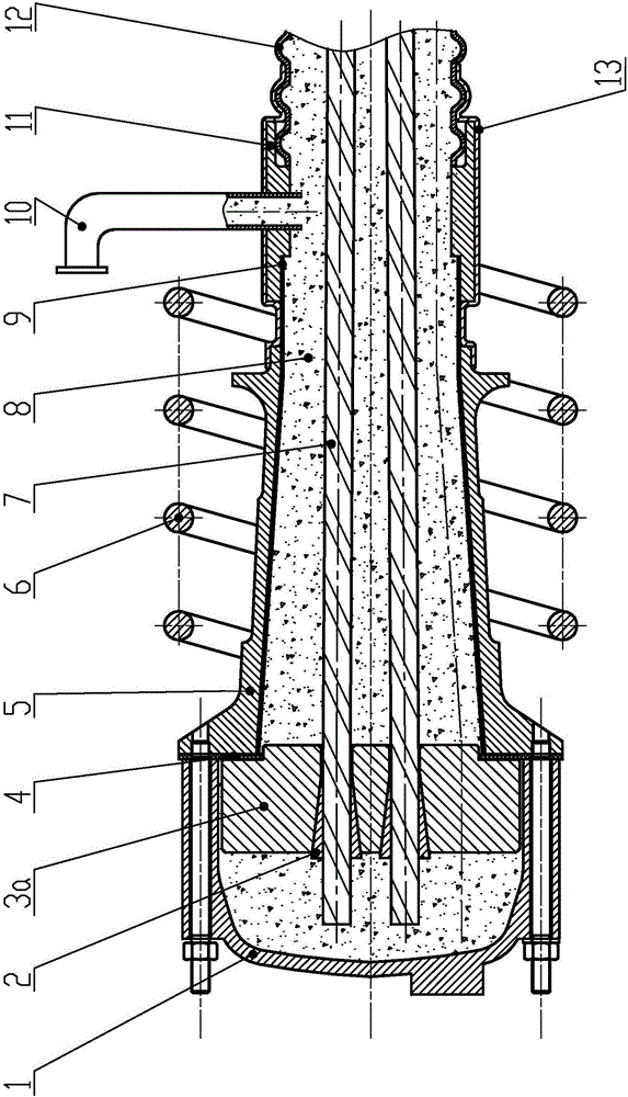
[0052] Such as figure 1 As shown, the electrical isolation prestressed anchorage system includes a working anchor plate 3, an anchor backing plate 5, a working clip 2, a prestressed tendon 7, a structural tendon 16 and a concrete 17 installed by a conventional method; the working clip 2 is installed on the working The anchor plate 3 is connected to the prestressed tendon 7; the prestressed tendon 7 runs through the working anchor plate 3, the anchor backing plate 5, and the bellows 12, and is fixed by the working clip 2 after being stretched; the spiral rib 6 is installed on the The outer circumferential position of the anchor pad 5 is coaxial with the anchor pad 5;

[0053] The electrically isolated prestressed anchoring system also includes insulating anchor covers 1, pressure-resistant insulating pads 4, insulating inner bushings 9, insulating connectors 11, insulating corrugated pipes 12 and other insulating ...

Embodiment 2

[0063] A detectable electrically isolated prestressed anchorage system:

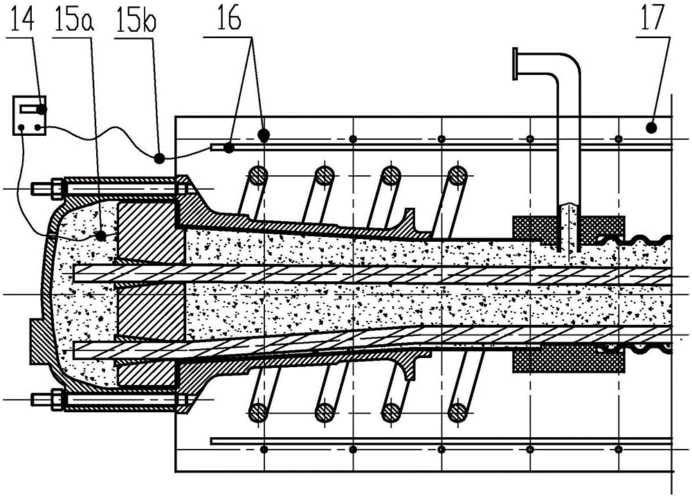
[0064] The basic structure of this embodiment is the same as that of Embodiment 1, and the difference from Embodiment 1 is that the electrical isolation prestressed anchor system also has an electrical isolation performance detector, and the electrical isolation performance detector includes an electric bridge meter 14, a connection anchor The inner conductor 15a of the system and the outer conductor 15b connected to the structural reinforcement 16 in the concrete, in the assembled state, one end of the inner conductor 15a is connected to the bridge meter 14, and the other end is connected to the working anchor plate or prestressed tendon of the electrically isolated prestressed anchorage system One end of the outer conductor 15b is connected with the bridge table 14, and the other end is connected with the structural rib 16 (see image 3 ).

[0065] As a transformation of Embodiment 1 and Embodiment 2 ...

Embodiment 3

[0074] A method for construction and installation of a detectable electrical isolation prestressed anchorage system, which is the installation method of the electrical isolation prestressed anchorage system described in Embodiment 2, is characterized in that it includes the following steps:

[0075] A. Install the embedded parts: install the spiral rib 6, the anchor plate 5, and the structural rib 16 in sequence; the outer wire 15b needs to be connected to the structural rib 16 during the pre-embedding process;

[0076] B. Install the insulating part: Insert the insulating inner bushing 9 into the anchor backing plate 5 and connect it tightly. One end of the connector 11 is mated and connected, and the insulating heat shrinkable sleeve 13 is installed at this time; the other end of the insulating connector 11 is matched with the insulating bellows. After the installation is completed, the heat shrinkable sleeve 13 is melted so as to completely cover the insulating inner bushing...


PUM

PropertyMeasurementUnit
Resistanceaaaaaaaaaa

Abstract

An electrical isolation prestressed anchorage system comprises a work anchor plate, an anchor backing plate, a work clamping piece, a prestressed tendon, a slurry body, a structure rib and concrete which are installed sequentially, and further comprises insulating parts including an insulating anchor cover, a crush-resistance insulating pad, an insulating neck bush, an insulating connector, an insulating corrugated pipe and the like; the insulating anchor cover is fixed to the anchor backing plate through a fastening part, so that the work anchor plate is completed covered; the work anchor plate is matched with the anchor backing plate, and the crush-resistance insulating pad is arranged between the end surface of the anchor backing plate and the end surface of the insulating neck bush; the crush-resistance insulating pad is of an annular structure, the insulating neck bush is installed in the anchor backing plate, the outer diameter of the insulating neck bush is matched with the inner diameter of the anchor backing plate, and the insulating neck bush is connected with the insulating corrugated pipe through the insulating connector; and the middle portion of the cylindrical surface of the insulating connector is provided with an assembling hole for being connected with a grout pipe for pouring of insulating slurry. The electrical isolation prestressed anchorage system is connected with an electrical isolation performance detector, and then an electrical isolation anchorage system capable of conducting detection can be formed. The electrical isolation prestressed anchorage system is reasonable in structure, quite convenient and quick in installation and construction and capable of achieving nondestructive testing of engineering.

Description

technical field [0001] The invention relates to a prestressed anchoring system, in particular to an electrically isolated prestressed anchoring system and a construction and installation method thereof. Background technique [0002] Prestressed concrete structures are the main stress-bearing components of large-scale infrastructure such as bridges and railways. Corrosion of prestressed tendons will affect the durability of prestressed concrete structures and even lead to prestressed failure; therefore, the anticorrosion of prestressed structures has always been Attention and research in the industry. [0003] For anti-corrosion protection of prestressed structures, it is necessary to isolate the prestressed tendons from the external environment to form an internal airtight structure to prevent the external environment from electrochemically corroding the prestressed tendons; and the usual anti-corrosion methods mostly use plastic bellows and plastic The form of the anchor c...

Claims


Application Information

Patent Timeline
IPC IPC(8): E01D21/00E04C5/12
CPCE01D21/00E04C5/12
Inventor 左海宁蒋业东黄颖温朝臣梁文昊曾航宇莫鲤木刘进经凤明唐彰丽
Owner LIUZHOU OVM MASCH CO LTD
Why Eureka
Try Eureka