Bearing reducer center wheel shell

A technology of reducer and center wheel, which is applied in the direction of mechanical equipment, belt/chain/gear, transmission parts, etc., and can solve the problem of large radial load of the reducer

Active Publication Date: 2017-06-13
重庆科谷机械有限公司
View PDF7 Cites 2 Cited by
  • Summary
  • Abstract
  • Description
  • Claims
  • Application Information

AI Technical Summary

Problems solved by technology

[0006] The present invention intends to provide the center wheel housing of the bearing reducer to solve the problem of large radial load of the existing reducer

Method used


Image

  • Bearing reducer center wheel shell
  • Bearing reducer center wheel shell

Examples


Embodiment Construction

[0017] The present invention will be described in further detail below by means of specific embodiments:

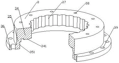
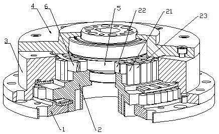
[0018] The reference signs in the drawings of the description include: bearing pressure plate 1, cage 2, retaining plate 21, inner row of balls 22, outer row of balls 23, housing 3, annular protrusion 341, groove 351, upper end plate 34, side Plate 35, lower end plate 36, slot 37, installation hole 38, assembly hole 39, cover plate 4, eccentric wheel 5, bearing ring 6.

[0019] The embodiment is basically as attached figure 1 As shown: the center wheel housing of the bearing reducer, including a cylindrical side plate 35, the upper part of the inner wall of the side plate 35 extends inward to form a ring-shaped upper end plate 34, and the lower part of the outer wall of the side plate 35 extends outward to form a ring Shaped lower end plate 36, the top of the upper end plate 34 is provided with a plurality of installation holes 38 along the circumferential direction. Th...


PUM


Abstract

The invention discloses a bearing reducer center wheel shell in the field of machine transmission. The bearing reducer center wheel shell comprises a cylindrical side plate, the upper portion of the inner wall of the side plate stretches inward to form a ring-shaped upper end plate, the lower portion of the outer wall of the side plate stretches outward to form a ring-shaped lower end plate, the top of the upper end plate is provided with a plurality of installation holes in the peripheral direction, the inner side wall of the upper end plate is provided with a plurality of vertical slots evenly formed in the peripheral direction, the tops of the slots are connected with the top of the upper end plate, the bottoms of the slots are connected with the bottom of the upper end plate, the section outline of each slot is in an arc shape, smooth transition is formed between every two adjacent slots, and the section outline of the side wall of the upper end plate is a ring-shaped track in a curtate epicycloid shape. By means of the bearing reducer center wheel shell, a bearing reducer has the advantages of being small in radial load, high in transmission ratio, uniform in load distribution, low in noise, low in abrasion, long in service life and high in carrying capacity.

Description

technical field [0001] The invention relates to the field of mechanical transmission, in particular to a center wheel housing of a bearing reducer. Background technique [0002] At present, there are two main types of reducers used in the field of robotics, one is the Rotate Vector reducer (RV reducer) of Japan's Nabtesco Teijin Seiki Co., Ltd., and the other is the harmonic reducer of Japan's Harmonic Drive. They almost monopolize The world's robot reducer. In the robot joints, because the RV reducer has higher rigidity and rotation accuracy, the RV reducer is generally placed on the base, the boom, the shoulder and other heavy load positions, and the harmonic reducer is placed on the forearm, arm, etc. wrist or hand. [0003] The transmission of the harmonic reducer is through the radial elastic deformation of the thin-walled flexible gear to realize the speed conversion and power transmission. The load-carrying capacity and transmission stiffness of the thin-walled flex...

Claims


Application Information

Patent Timeline
Patent Type & Authority Applications(China)
IPC IPC(8): F16H57/02F16H57/031F16H57/08
CPCF16H57/02F16H57/031F16H57/08F16H2057/02069
Inventor 李亚明
Owner 重庆科谷机械有限公司
Why Eureka
Try Eureka