Air return pipe assembly for refrigerator

An air return pipe and assembly technology, which is applied in the field of refrigerator air return pipe assemblies, can solve the problems of insignificant cold and heat transfer effect, increased material cost, small contact area, etc., and achieves the effects of good implementation effect, improved work efficiency and simple operation.

Inactive Publication Date: 2017-06-13
HEFEI MAITUO NEW MATERIAL TECH CO LTD
View PDF0 Cites 2 Cited by
  • Summary
  • Abstract
  • Description
  • Claims
  • Application Information

AI Technical Summary

Problems solved by technology

However, when the air return pipe and the capillary are connected by a heat-shrinkable sleeve or wrapped and fixed with aluminum foil or tape, the contact area between the air return pipe and the capillary is small, and the heat transfer effect is not obvious, especially The capillary is easy to fall off after long-term use of aluminum foil and adhesive tape wrapping
Although the sleeve connection is used to prevent the capillary from falling off, the material cost is increased, and there is a defect that the contact area between the return air pipe and the capillary is small
Soldering is used to avoid the capillary from falling off, but if it is spot welding, there is a defect that the contact area between the return air pipe and the capillary is small; if it is full welding, the capillary is easy to be damaged, and the operation is difficult and costly

Method used


Image

  • Air return pipe assembly for refrigerator
  • Air return pipe assembly for refrigerator
  • Air return pipe assembly for refrigerator

Examples


Embodiment 1

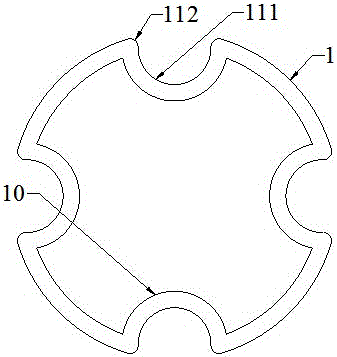
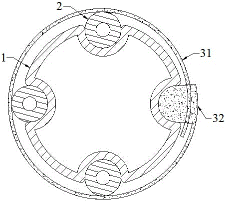
[0020] Such as Figure 1~3 As shown, the air return pipe assembly of the refrigerator includes a return air pipe 1, a capillary 2 and a bandage. The capillary 2 is arranged on the outside of the air return pipe 1, and four axial shafts matching the capillary 2 are arranged on the outside of the air return pipe 1 by stamping technology. Stamping groove, due to the stamping groove made by stamping technology, an arc-shaped convex part 10 corresponding to the stamping groove is formed inside the return air pipe 1, and the convex part 10 makes the inner wall of the return air pipe 1 and the refrigerant in the return air pipe 1 The contact area between them is increased, thereby shortening the heat transfer time and improving the heat transfer efficiency; the stamping groove cooperates with the capillary 2 to maximize the fit between the capillary 2 and the stamping groove, and increases the gap between the capillary 2 and the return air pipe 1 The contact area between the capillar...

Embodiment 2

[0023] Such as Figure 4~5 As shown, on the basis of Embodiment 1, an axial functional groove 113 recessed to the inside of the air return pipe 1 is stamped in the middle of the locking part 111, and an arc corresponding to the functional groove 113 is also formed on the convex part 10. Shaped protrusion 101, the protrusion 101 further increases the contact area between the inner wall of the return air pipe 1 and the refrigerant in the return air pipe 1, thereby further shortening the heat transfer time and further improving the heat transfer efficiency; the functional groove 113 is also further improved The outer surface area of ​​the air return pipe 1 is reduced, and the notch of the functional groove 113 is relatively small. Under the barrier of the capillary 2, the functional groove 113 is easy to form a closed sealed cavity, and the water vapor in the air is liquefied and filled in the sealed cavity, thereby being able to Further promote heat exchange between the capillar...

Embodiment 3

[0025] Such as Figure 6 As shown, on the basis of Embodiment 2, V-shaped axial long grooves 12 are provided on the outside of the air return pipe 1 , and the long grooves 12 are symmetrically distributed around the axis of the air return pipe 1 . The elongated groove 12 cannot further improve the mechanical strength of the air return pipe 1, and the elongated groove 12 can further increase the outer surface area of ​​the air return pipe 1; temperature, the outer surface area of ​​the air return pipe 1 increases, which can further promote the preheating of the refrigerant in the air return pipe 1 before entering the compressor, and improve the efficiency of the compressor; in addition, the long groove 12 is V-shaped, which not only reduces the Not only is the slotting difficult, but also the surface area of ​​the elongated slot 12 can be increased to the maximum, killing two birds with one stone.


PUM


Abstract

The invention relates to an air return pipe assembly for a refrigerator. The air return pipe assembly comprises an air return pipe, a capillary tube and a binding tape, wherein a plurality of axial punching grooves which sink towards the inside of the air return pipe are formed in the outer side of the air return pipe; each punching groove comprises a locking part and a guide part; and the air return pipe is fixedly connected with the capillary tube through the binding tape. According to the air return pipe assembly for the refrigerator, the punching grooves and a strip slot are formed in the air return pipe, so that the internal and external superficial areas of the air return pipe are significantly increased, cold and heat exchange efficiency between the capillary tube and the air return pipe is improved, a refrigerant in the air return pipe is prompted to be fully preheated before entering a compressor, the work efficiency of the compressor is improved, and the air return pipe assembly is more energy-saving and convenient. The air return pipe is fixedly connected with the capillary tube through the binding tape, so that the operation is simple, the cost is low, the fixed structure is stable, the capillary tube can be effectively prevented from being separated from the air return pipe, the capillary tube is not damaged, and the implementation effect is good.

Description

technical field [0001] The invention relates to a refrigerator air return pipe assembly, which belongs to the technical field of refrigerator assemblies. Background technique [0002] At present, in the refrigerator refrigeration system, it is necessary to reduce the temperature of the capillary with the help of the low temperature of the return air pipe. In the refrigeration system, the temperature of the liquid in the capillary is higher than the temperature of the refrigerant in the return air pipe, so the capillary is wrapped around the return air pipe. The outer side of the trachea, which can not only promote the cooling of the liquid in the capillary, ensure its complete evaporation in the evaporator, but also make the refrigerant passing through the return pipe preheat before entering the compressor, improving the efficiency of the compressor. However, when the air return pipe and the capillary are connected by a heat-shrinkable sleeve or wrapped and fixed with alumin...

Claims


Application Information

Patent Timeline
Patent Type & Authority Applications(China)
IPC IPC(8): F25B41/00F25B41/06F25B41/31F25B41/40
CPCF25B41/00F25B2500/18F25B41/30
Inventor 赵迎辉
Owner HEFEI MAITUO NEW MATERIAL TECH CO LTD
Why Eureka
Try Eureka