Experiment device and experiment method for simulating thermal jet flow interference

An experimental method, jet flow technology, applied in the direction of measuring device, aerodynamic test, machine/structural component test, etc., can solve the problems of high cost of engine experiment, difficult experiment, wind tunnel corrosion, etc., and achieve strong engineering practicality Value, reduced experiment difficulty, low heat load effect

Inactive Publication Date: 2017-06-13
INHALE HYPERSONIC TECH RES CENT UNIT 63820 OF PLA
View PDF5 Cites 25 Cited by
  • Summary
  • Abstract
  • Description
  • Claims
  • Application Information

AI Technical Summary

Problems solved by technology

The experiment is more difficult and costly, and may cause certain corrosion to the wind tunnel
The cost of carrying out engine experiments with tail jets in the combustion wind tunnel is relatively high; at the same time, due to the limited size of the current combustion wind tunnel, it is difficult to carry out the interference experiment of the tail nozzle in the existing combustion wind tunnel under real conditions, so , it is necessary to carry out wake jet interference experiments in conventional wind tunnels

Method used


Image

  • Experiment device and experiment method for simulating thermal jet flow interference
  • Experiment device and experiment method for simulating thermal jet flow interference

Examples


Embodiment 1

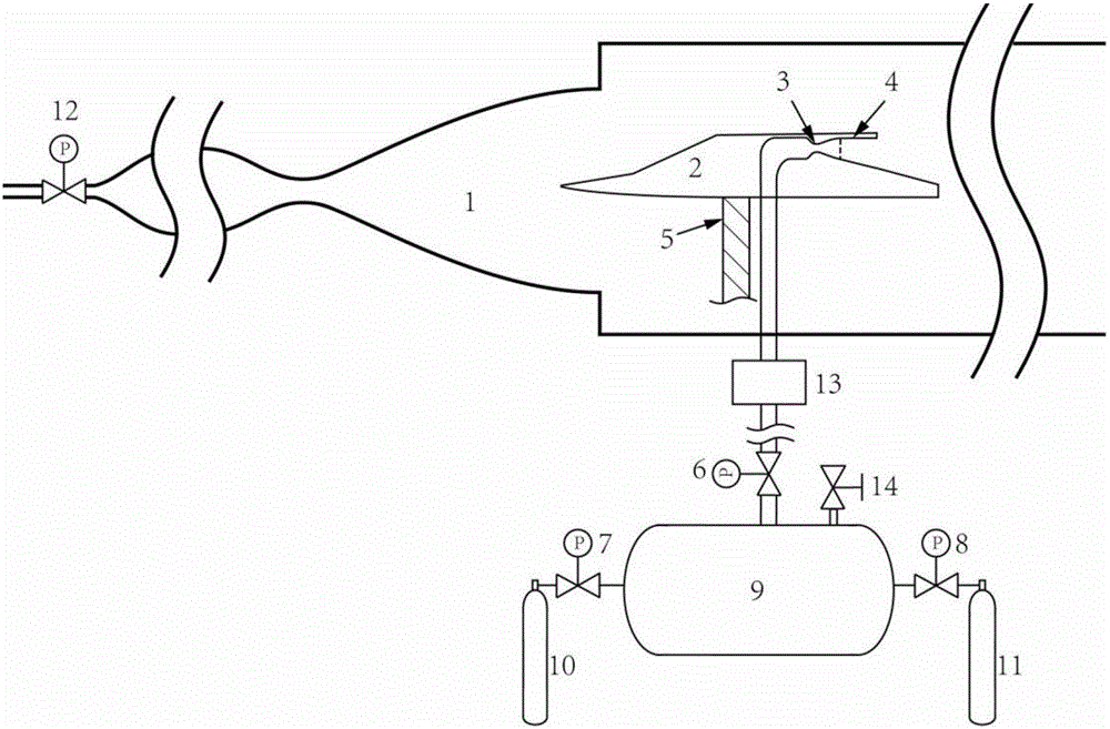
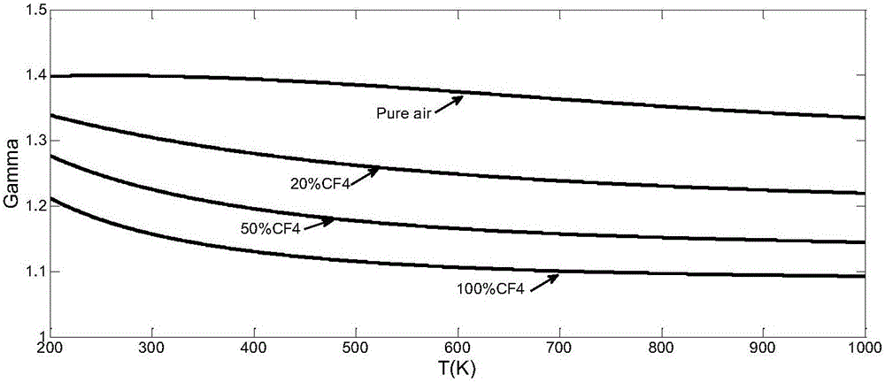
[0029] An experimental method for simulating thermal jet interference. The wind source is compressed and expanded by a hypersonic wind tunnel 1 and then becomes a hypersonic air flow to provide the outer flow for the experiment. CF4 or SF6 gas is mixed with air to provide the inner jet flow for the experiment. Control the molar mixing ratio and temperature of CF4 / SF6 gas and air to obtain the specific heat ratio required by the experiment, so as to meet the requirements of the jet specific heat ratio simulation in the experiment.

Embodiment 2

[0031] This embodiment provides an experimental method for simulating thermal jet interference. Before the experiment, the required specific heat ratio is determined according to the experimental state, and the molar ratio of CF4 or SF6 gas and air is calculated according to the specific heat ratio. The partial pressure ratio of CF4 or SF6 gas and air is obtained by the theorem of partial pressure. During the experiment, the pressure of CF4 or SF6 gas and the pressure of air are controlled according to this partial pressure ratio, and the mixed gas is heated to the required experimental temperature. Flow into the Laval inner nozzle 3, so as to realize the specific heat ratio required by the experiment, and generate the model nozzle inlet conditions required for the experiment, and then the mixed gas flows into the model nozzle 4, so as to carry out the thermal performance experiment of the model nozzle 4 Research.

[0032] The experimental specific heat ratio is between 1.1 an...

Embodiment 3

[0036] Such as figure 1 As shown, this embodiment provides an experimental device for simulating thermal jet interference, including a hypersonic wind tunnel 1, an experimental model 2 inside the hypersonic wind tunnel 1, a bracket 5 supporting the experimental model 2, and fixed on the bracket 5 The Laval inner nozzle 3, the model nozzle 4 connected with the Laval inner nozzle 3, the Laval inner nozzle 3 is used to provide the required inlet flow field for the model nozzle 4, and the valve 12 is connected between the wind source and the hypersonic speed The pipeline of the wind tunnel is used as a switch to open the hypersonic wind tunnel. The inlet of the Laval inner nozzle 3 is connected to the outlet of the heater 13, and the inlet of the heater 13 is connected to the outlet of the gas storage tank 9 through the dynamic feedback regulating valve 6. One inlet of the gas tank 9 is connected to the air cylinder 10 through the first electromagnetic pressure regulating valve 7 ...


PUM


Abstract

The invention provides an experiment device and an experiment method for simulating thermal jet flow interference. The experiment device comprises a hypersonic wind tunnel, an experiment model, a bracket, a Laval internal nozzle, a model nozzle, a heater, an air storage tank, an air cylinder and a CF4/SF6 gas cylinder, wherein an air source is compressed and expanded through the hypersonic wind tunnel and then becomes hypersonic airflow to provide an experiment with external flow; a CF4/SF6 gas is mixed with air and then provides the experiment with internal jet flow; the specific heat ratio required by the experiment is obtained through controlling the molar mixing ratio and the temperature of the CF4/SF6 gas and air, so that the requirements on specific heat ratio simulation of the jet flow in the experiment are met; and simulation of a jet flow interference experiment of the specific heat ratio of the jet flow is achieved in a common wind tunnel. The experiment method has the advantages of being relatively long experiment time, free of pollution, low in thermal load and low in cost, and therefore, the experiment method can be used as an effective means for evaluating the performance of the spray pipe of a hypersonic aerocraft.

Description

technical field [0001] The invention belongs to the experimental field of internal and external flow interference of a rear body tail nozzle of a hypersonic vehicle, and in particular relates to an experimental device and an experimental method for simulating thermal jet flow interference. Background technique [0002] For airplanes, missiles, rockets and various aerospace vehicles, there is complex mutual interference between the exhaust (jet flow) of the propulsion system and the airflow outside the vehicle. The jet flow affects the turbulence characteristics around the relevant parts of the aircraft, and changes the lift-drag characteristics, stability, maneuverability and rudder surface efficiency. The outflow may also affect the flow characteristics in the engine tailpipe, thereby affecting the thrust characteristics and suction characteristics, and ultimately will affect the flight performance. The amount of influence is related to the shape of the aircraft, flight al...

Claims


Application Information

Patent Timeline
Patent Type & Authority Applications(China)
IPC IPC(8): G01M9/04G01M9/08
CPCG01M9/04G01M9/08
Inventor 贺旭照秦思周凯卫锋周正张俊韬倪鸿礼胡俊逸
Owner INHALE HYPERSONIC TECH RES CENT UNIT 63820 OF PLA
Why Eureka
Try Eureka