
Intelligent space positioning system and space positioning method for laser pan-tilt

An intelligent space and positioning system technology, applied in the field of testing, can solve the problems that the transmitting and receiving antennas cannot move the measurement signal synchronously, the space positioning cannot reach the accurate value, and the inconvenience of use, so as to increase the effective battery life, reduce the deployment time, and solve the problems Troublesome Effects

Pending Publication Date: 2017-06-13
赵怡
View PDF8 Cites 11 Cited by
  • Summary
  • Abstract
  • Description
  • Claims
  • Application Information

AI Technical Summary

Problems solved by technology

[0004] (1) The measurement accuracy of the existing technology is low. The main problem is that the technology of the hardware components is limited. The spatial positioning of the moving object will be inaccurate due to the untimely response of the hardware. At the same time, the influence of radio wave interference will increase the use of the site. limitations
In the actual use of radio waves, due to hardware reasons, the precise positioning cannot meet the actual requirements, and the measurement accuracy cannot be satisfied;
[0005] (2) The use of the existing technology is relatively inconvenient. The existing technology requires four transceiver modules to operate at the same time to realize the positioning of the spatial position. Correspondingly, it is inconvenient to deploy and recover equipment at multiple points at the beginning of the measurement. ;
[0006] (3) The fatal shortcoming of the existing technology is that the practical radio wave communication measures the distance information of each sending and receiving point, which is limited by the error of the hardware equipment, the measurement accuracy cannot meet the needs of precise surveying and mapping, and the spatial positioning cannot reach the required precise value
In addition, during wireless signal transmission, measurement signal loss will occur due to the inability to synchronize the movement of the transceiver antenna.

Method used


Image

  • Intelligent space positioning system and space positioning method for laser pan-tilt
  • Intelligent space positioning system and space positioning method for laser pan-tilt
  • Intelligent space positioning system and space positioning method for laser pan-tilt

Examples


Embodiment 1

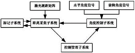
[0036] attached figure 1 It is a schematic diagram of the composition frame of the laser pan-tilt intelligent space positioning system. The pan-tilt is an outdoor surveying and mapping equipment. The laser scanning pan-tilt is installed on a tripod, and the laser is fixed on the scanning pan-tilt. By adjusting the rotation angle of the pan-tilt, it can Carry out surveying and mapping work at a specific angle. The laser pan / tilt intelligent space positioning system in the present invention includes a distance acquisition subsystem, an angle control subsystem, a marking subsystem and a control management subsystem. The distance acquisition subsystem receives information from the marking subsystem, and the received information is transmitted to the control management The subsystem, in the process of receiving information, needs to adjust the direction of the distance acquisition subsystem through the angle control subsystem according to the position of the marking subsystem, so ...

Embodiment 2

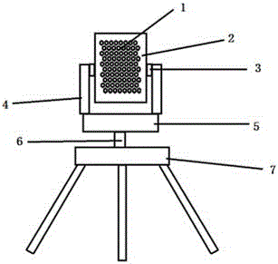
[0055] On the basis of Embodiment 1, the arrangement of the laser ranging probes 1 on the laser probe carrier plate 2 is further designed, and the arrangement of the laser ranging probes 1 is a quadrilateral rectangular array or a hexagonal honeycomb array arranged in parallel. , forming a laser array. The laser array simultaneously monitors distance information from the same direction, and each laser ranging probe 1 collects independent distance information.

[0056] During the monitoring process, position locking is required, and the probes arranged in a quadrilateral rectangular array are shown in the attached Figure 5 As shown, the state (1) is the initial state of detecting the high-light body. When the high-light body faces the center of the laser array, the four laser ranging probes in the center of the array will detect the same (within the error range) distance information, then it is considered that at this moment The high-light body has been aligned and aimed; the...


PUM


Abstract

The invention discloses an intelligent space positioning system and space positioning method for a laser pan-tilt. The space positioning system comprises a distance acquisition subsystem, an angle control subsystem and a marker subsystem, wherein the distance acquisition subsystem comprises a probe array formed by laser ranging probes; the probe array follows the marker subsystem and monitors distance information between the probe array and the marker subsystem from the same direction; each laser ranging probe collects independent distance information separately; the angle control subsystem controls a level angle and a pitch angle of the distance acquisition subsystem and makes the distance acquisition subsystem aligned at the marker subsystem; and the marker subsystem provides the distance acquisition subsystem with an alignment signal, receives alignment measurement operation of the distance acquisition subsystem and is matched with correction lock operation of the angle control subsystem. According to the system, large-range measurement and accurate positioning can be achieved by employing laser ranging, meanwhile, the anti-jamming capability of equipment is improved, and the measurement accuracy can be further improved by using the space positioning method.

Description

technical field [0001] The invention relates to the technical field of testing, in particular to a laser pan-tilt intelligent space positioning system and a space positioning method. Background technique [0002] In the existing wireless communication ranging equipment, it is mainly composed of four parts: three wireless signal transmitting and receiving points on the ground and one wireless signal transmitting and receiving point in the air. Its main principle is to use the divergent propagation of radio waves, measure the time of several sending and receiving points, and calculate the distance information of each sending and receiving point. Then by bringing it into the calculation, the relative position information of the sending and receiving points in the air is obtained. [0003] When the above technology is used for large-scale testing and positioning measurement, there are the following problems and shortcomings: [0004] (1) The measurement accuracy of the existin...

Claims


Application Information

Patent Timeline
Patent Type & Authority Applications(China)
IPC IPC(8): G01S17/48G01S7/497G05D3/12
CPCG05D3/12G01S7/497G01S17/48
Inventor 赵怡
Owner 赵怡
Learn More