Method for forming multi-focus bionic compound eye structure
A bionic compound eye, multi-focus technology, applied in optics, lenses, instruments, etc., can solve the problem of single focal length of bionic compound eyes, achieve the effect of strong universality and improve the level of preparation technology
- Summary
- Abstract
- Description
- Claims
- Application Information
AI Technical Summary
Problems solved by technology
Method used
Image


Examples
Embodiment Construction
[0028] The present invention will be described in detail below in conjunction with the accompanying drawings and specific embodiments. But the following examples are limited to explain the present invention, and the protection scope of the present invention should include the entire content of the claims, and through the following examples, those skilled in the art can realize the entire contents of the claims of the present invention.
[0029] The forming method of a kind of multi-focus bionic compound eye structure in the specific embodiment is as follows:
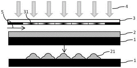
[0030] figure 1 Schematic diagram of photoresist forming preparation for planar continuous surface-shaped multifocal compound eye structure. Choose quartz as substrate 1, pretreat its surface, soak it in acetone for 10 minutes, remove the organic matter on the surface, then clean the residual acetone with alcohol, and finally rinse the substrate with ultrapure water. Spin-coat photoresist 2 on the surface of the substr...
PUM
 Abstract
Description
Claims
Application Information
 - R&D
- Intellectual Property
- Life Sciences
- Materials
- Tech Scout
- Unparalleled Data Quality
- Higher Quality Content
- 60% Fewer Hallucinations
Browse by: Latest US Patents, China's latest patents, Technical Efficacy Thesaurus, Application Domain, Technology Topic, Popular Technical Reports.
© 2025 PatSnap. All rights reserved.Legal|Privacy policy|Modern Slavery Act Transparency Statement|Sitemap|About US| Contact US: help@patsnap.com