Optical module

A technology of optical modules and optical sub-modules, which is applied in the field of optical modules and can solve problems such as the reduction of optical fiber coupling efficiency

Active Publication Date: 2017-06-13
HISENSE BROADBAND MULTIMEDIA TECH
View PDF6 Cites 1 Cited by
  • Summary
  • Abstract
  • Description
  • Claims
  • Application Information

AI Technical Summary

Problems solved by technology

[0004] When the optical module is assembled or inserted into the optical module cage, the housing will shake. Since the adapter is clamped in the housing, and the optical port is integrally designed with the housing, when the housing shakes , the adapter is easy to move relative to the housing, but the optical port will not move relative to the housing, which will cause relative movement between the adapter and the optical port, resulting in optical fiber The coupling efficiency is reduced

Method used


Image

  • Optical module
  • Optical module
  • Optical module

Examples


Embodiment Construction

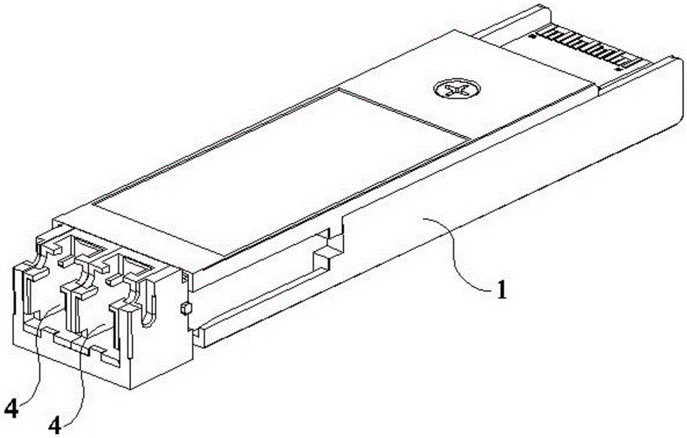
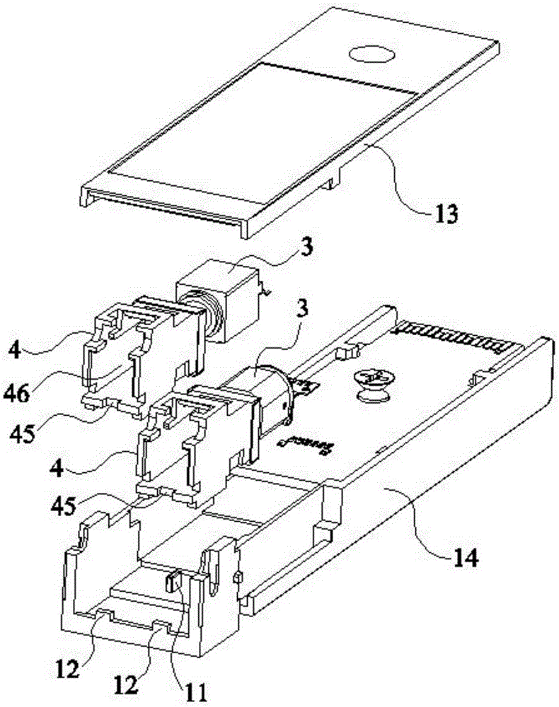
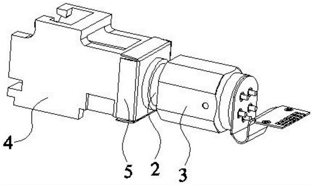
[0015] The following will clearly and completely describe the technical solutions in the embodiments of the present invention with reference to the accompanying drawings in the embodiments of the present invention. Obviously, the described embodiments are only some, not all, embodiments of the present invention. Based on the embodiments of the present invention, all other embodiments obtained by persons of ordinary skill in the art without making creative efforts belong to the protection scope of the present invention.

[0016] In describing the present invention, it is to be understood that the terms "center", "upper", "lower", "front", "rear", "left", "right", "vertical", "horizontal", The orientations or positional relationships indicated by "top", "bottom", "inner", "outer", etc. are based on the orientations or positional relationships shown in the drawings, and are only for the convenience of describing the present invention and simplifying the description, rather than in...


PUM


Abstract

The invention discloses an optical module and relates to the technical field of optical fiber communication. The optical module can avoid relative motion between an adapter and an optical port member to ensure the coupling efficiency of an optical fiber. The optical module comprises a case, inside which the adapter and an optical sub-module are arranged and fixed to each other; the optical port member is arranged inside the case and on one side of the adapter, which is away from the optical sub-module, and one end of the optical port member, which is away from the adapter, is provided with an opening; the end surface of the optical port member, which is away from the adapter, is provided with a through hole, the adapter can penetrate the through hole and fix the optical port member, and the optical fiber can extends into the adapter via the opening.

Description

technical field [0001] The invention relates to the technical field of optical fiber communication, in particular to an optical module. Background technique [0002] In optical fiber communication technology, optical signals are used as information carriers for high-speed, long-term, and reliable information transmission. The function of the optical module is photoelectric conversion, that is, the sending end converts the electrical signal into an optical signal, and after transmission through the optical fiber, the receiving end converts the optical signal into an electrical signal. [0003] The optical module in the prior art includes a housing, an adapter and an optical sub-module fixed to each other, the adapter and the optical sub-module are clamped in the housing, and an optical port is also arranged in the housing, so The optical port is designed integrally with the housing, and the optical fiber can be inserted into the adapter through the optical port, so that the ...

Claims


Application Information

Patent Timeline
IPC IPC(8): G02B6/42
Inventor 崔伟刘寅龙潘红超于琳
Owner HISENSE BROADBAND MULTIMEDIA TECH
Why Eureka
Try Eureka