
Strength calculation method of boat-shaped structure object

A strength calculation and structure technology, applied in the direction of calculation, design optimization/simulation, special data processing applications, etc., can solve the problem that the design model cannot meet the design requirements of the ship type, the uncertainty of the hull weight control of heavy cargo, the system and labor costs increase in requirements, etc.

Inactive Publication Date: 2017-06-13
708TH RES INST OF CSSC
View PDF1 Cites 6 Cited by
  • Summary
  • Abstract
  • Description
  • Claims
  • Application Information

AI Technical Summary

Problems solved by technology

[0002] With the increase of ship design size and design requirements, the two-dimensional plane design model can no longer meet the current ship design requirements
[0003] Taking the ultra-large semi-submersible ship as an example, in addition to the fact that the scale ratio of this ship is far from meeting the specification requirements, its special structural layout, strict hull weight control, tall forecastle and independently movable stern pontoon structure and special Due to the uncertainty of the operation method and heavy cargo, it is necessary to achieve the macroscopic control of the hull structure stiffness and strength under the strict control target of hull steel weight in the early stage of structural design, which is difficult for the traditional mid-section design technology. Good satisfaction; so it is necessary to add experience judgment factors to assist the design, causing greater inconvenience
[0004] On the other hand, the current finite element analysis method has complex and diverse algorithms. Although various situations have been accurately analyzed, the requirements for system and labor costs are constantly increasing, resulting in a large waste of resources.

Method used


Image

  • Strength calculation method of boat-shaped structure object
  • Strength calculation method of boat-shaped structure object
  • Strength calculation method of boat-shaped structure object

Examples


Embodiment Construction

[0024] In order to make it easy to understand the technical means, creative features, goals and effects achieved by the present invention, the following examples are combined with the appended figure 1 The technical solutions provided by the present invention are described in detail, but the following content is not intended as a limitation of the present invention.

[0025] A method for calculating the strength of a ship-shaped structure. A ship-shaped structure is provided. The ship-shaped structure includes an outer plate, a transverse bulkhead, a transverse web frame and a frame, and the specific steps include

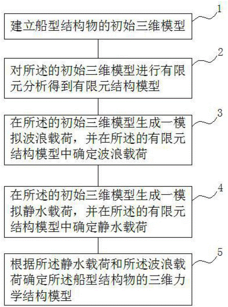
[0026] Step 1, providing a first processing unit to establish an initial three-dimensional model of a ship-shaped structure;

[0027] In step 2, a second processing unit is provided to perform finite element analysis on the initial 3D model to obtain a finite element structural model; in step 2, an orthotropic plate element is introduced to determine the aggregates...


PUM


Abstract

The invention provides a strength calculation method of a boat-shaped structure object, and provides the boat-shaped structure object, wherein an outer plate, a transverse cabin wall, a transverse strength framework and a bone material are arranged on the boat-shaped structure object. The method comprises the following concrete steps that 1, building an initial three-dimensional model of the boat-shaped structure object; 2, performing finite element analysis on the initial three-dimensional model to obtain a finite element structure model; 3, generating a simulation wave load on the initial three-dimensional model; determining the wave load in the finite element structure model; 4, generating a simulation still water load in the initial three-dimensional model; determining the still water load in the finite element structure model; 5, determining the three-dimensional mechanical structure model of the boat-shaped structure object according to the still water load and the wave load. The method has the advantages that the operation is convenient, simplicity and reliability are realized; more importantly, the model reduces the system operation cost; the efficiency is improved; the reliability is ensured.

Description

technical field [0001] The invention relates to the technical field of ship modeling, in particular to a method for calculating the strength of ship-shaped structures. Background technique [0002] With the increase of ship design size and design requirements, the two-dimensional plane design model can no longer meet the current ship design requirements. [0003] Taking the ultra-large semi-submersible ship as an example, in addition to the fact that the scale ratio of this ship is far from meeting the specification requirements, its special structural layout, strict hull weight control, tall forecastle and independently movable stern pontoon structure and special Due to the uncertainty of the operation method and heavy cargo, it is necessary to achieve the macroscopic control of the hull structure stiffness and strength under the strict control target of hull steel weight in the early stage of structural design, which is difficult for the traditional mid-section design tech...

Claims


Application Information

Patent Timeline
Patent Type & Authority Applications(China)
IPC IPC(8): G06F17/50
CPCG06F30/15G06F30/23
Inventor 孙雪荣
Owner 708TH RES INST OF CSSC
Learn More