Steel ladle

A ladle and cladding technology, which is applied in the direction of casting molten material containers, metal processing equipment, casting equipment, etc., can solve the problems of reducing the service life of the ladle, sticking slag, and long replacement time of the pressure plate, so as to improve the anti-deformation ability and prolong the service life of the ladle. The effect of service life and reducing labor intensity

Inactive Publication Date: 2017-06-16
李晓娜
View PDF0 Cites 0 Cited by
  • Summary
  • Abstract
  • Description
  • Claims
  • Application Information

AI Technical Summary

Problems solved by technology

[0004] When the above-mentioned ladle is in use, the sticky slag on the edge of the ladle gradually increases, and the molten steel cannot enter the LF and RH molten steel refining furnaces after the edge of the ladle is super high.
When dealing with sticky slag along the ladle, it is easy to damage the pouring lining and brick lining along the ladle, and is forced to repair the ladle edge off-line, which affects the turnover rate of the ladle and the service life of the lining
In order to solve the above problems, a pressure plate is provided at the edge of the cladding. The pressure plate is an ordinary steel plate, which is welded to the edge of the cladding in blocks. The service life of the edge, so the pressure plate needs to be replaced regularly
Due to the poor working environment on site and the long replacement time of the pressure plate, the labor intensity of the maintenance personnel is high

Method used


Image

  • Steel ladle
  • Steel ladle
  • Steel ladle

Examples


Embodiment 3

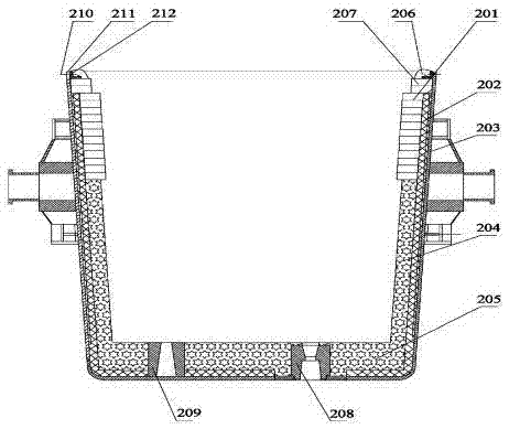
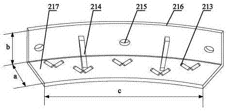
[0031] Embodiment 3 The embodiment of the present invention provides a ladle processing method, as shown in FIG. 2 and FIG. 4 , including the steps: Step S10: fixing the pressing plate 212 on the cladding 211 by bolts, the structure of the pressing plate 212 As shown in Example 1; step S21: paste the insulation layer 203 on the inner wall of the cladding 211, and use the permanent lining pouring construction tire film to pour the permanent lining castable as a whole, and bake on a low fire for 8h-16h to form the permanent lining 202; Step S22: Use the working lining pouring construction tire membrane to pour the wall-wrapped working lining castable as a whole, install the nozzle seat brick 208 and the breathable seat brick 209, and naturally cure for 8h-16h to form the wall-wrapped pouring lining 204 and the bottom-wrapping pouring lining 205 respectively; Build cladding wall lining brick 201, masonry cladding lining brick 207; Step S30: pour cladding edge castable, cladding ed...


PUM

PropertyMeasurementUnit
Lengthaaaaaaaaaa
Widthaaaaaaaaaa
Heightaaaaaaaaaa

Abstract

The embodiment of the invention discloses a steel ladle. The steel ladle comprises a ladle cladding, a working lining and a pressing plate. The working lining is arranged in the ladle cladding and comprises ladle wall lining bricks, ladle edge lining bricks and a ladle edge pouring lining, wherein the ladle edge lining bricks are built on the ladle wall lining bricks, the pressing plate is arranged between the ladle edge lining bricks and the ladle edge pouring lining and fixed to the ladle cladding, the pressing plate is made of a heat-resistant cast iron pressing plate and comprises a bottom plate, brace bars and a fixing plate matched with the inner wall of the ladle cladding, the bottom plate extends in the thickness direction of the fixing plate, the fixing plate is fixed to the ladle cladding through bolts, and the bracing bars are fixed to the bottom plate and the fixing plate respectively.

Description

technical field [0001] The invention relates to the field of metallurgical equipment, in particular to a steel ladle. Background technique [0002] The ladle is a container for storing molten steel and an integral part of refining equipment. A traditional ladle structure is shown in Figure 1, the ladle includes a cladding 111, an insulating layer 103 and a lining (not shown in the figure), wherein the insulating layer 103 is arranged between the cladding 111 and the lining; the lining includes The working lining and the permanent lining 102, the working lining is in direct contact with the molten steel, and the permanent lining 102 is in direct contact with the insulation layer 103; the working lining includes the bottom pouring lining 105, the wall pouring lining 104, the wall lining brick 101, The lining bricks 107 and the pouring lining 106, wherein, the bottom casting lining 105 and the wall casting lining 104 are integrally cast through the working lining casting const...

Claims


Application Information

Patent Timeline
IPC IPC(8): B22D41/02B22D41/00
Inventor 李晓娜
Owner 李晓娜
Why Eureka
Try Eureka