
Engine water cooling device

A water-cooling device and engine technology, applied in engine cooling, engine components, machines/engines, etc., can solve problems such as engine overheating, coolant boiling, loss, etc., and achieve fast heat dissipation, reduced energy consumption, and simple structure. Effect

Inactive Publication Date: 2017-06-16
WUHU YONGYU AUTOCAR INDAL
View PDF0 Cites 4 Cited by
  • Summary
  • Abstract
  • Description
  • Claims
  • Application Information

AI Technical Summary

Problems solved by technology

More and more car owners choose to travel or go on a business trip by car to drive the car for a long distance, which will cause the car engine to overheat, which may easily cause problems such as boiling of the coolant and excessive engine temperature. In this case, the car owner needs to stop and wait Continue driving after the engine has cooled down, which will cause damage if the owner is in an emergency

Method used


Image

  • Engine water cooling device
  • Engine water cooling device

Examples


Embodiment Construction

[0018] Below, the technical solution of the present invention will be described in detail through specific examples.

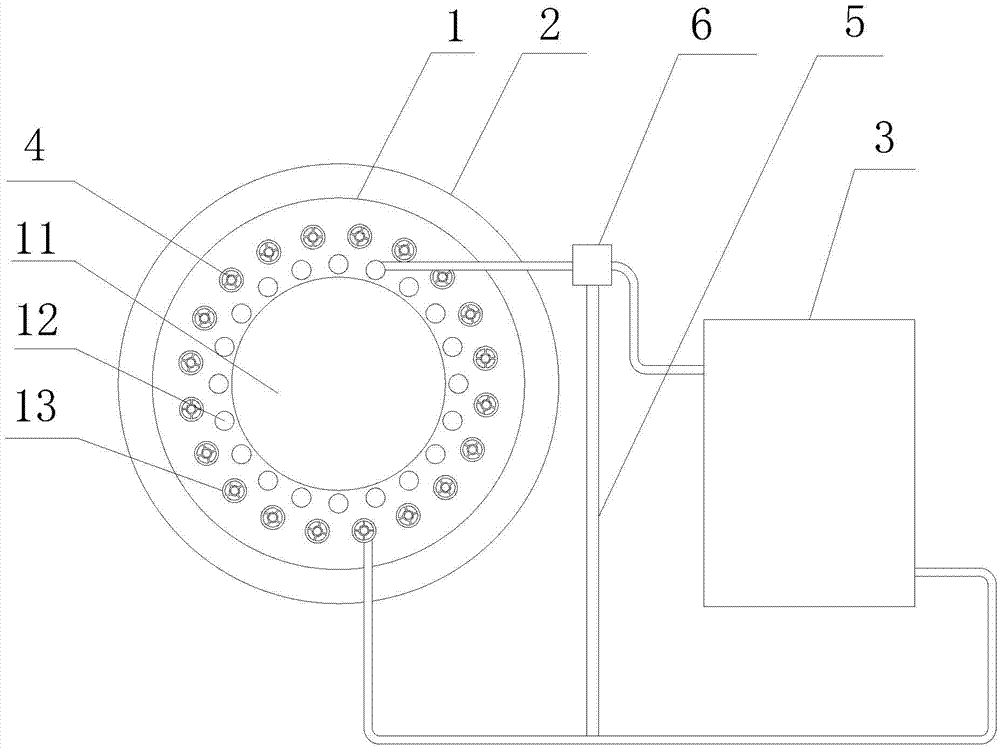
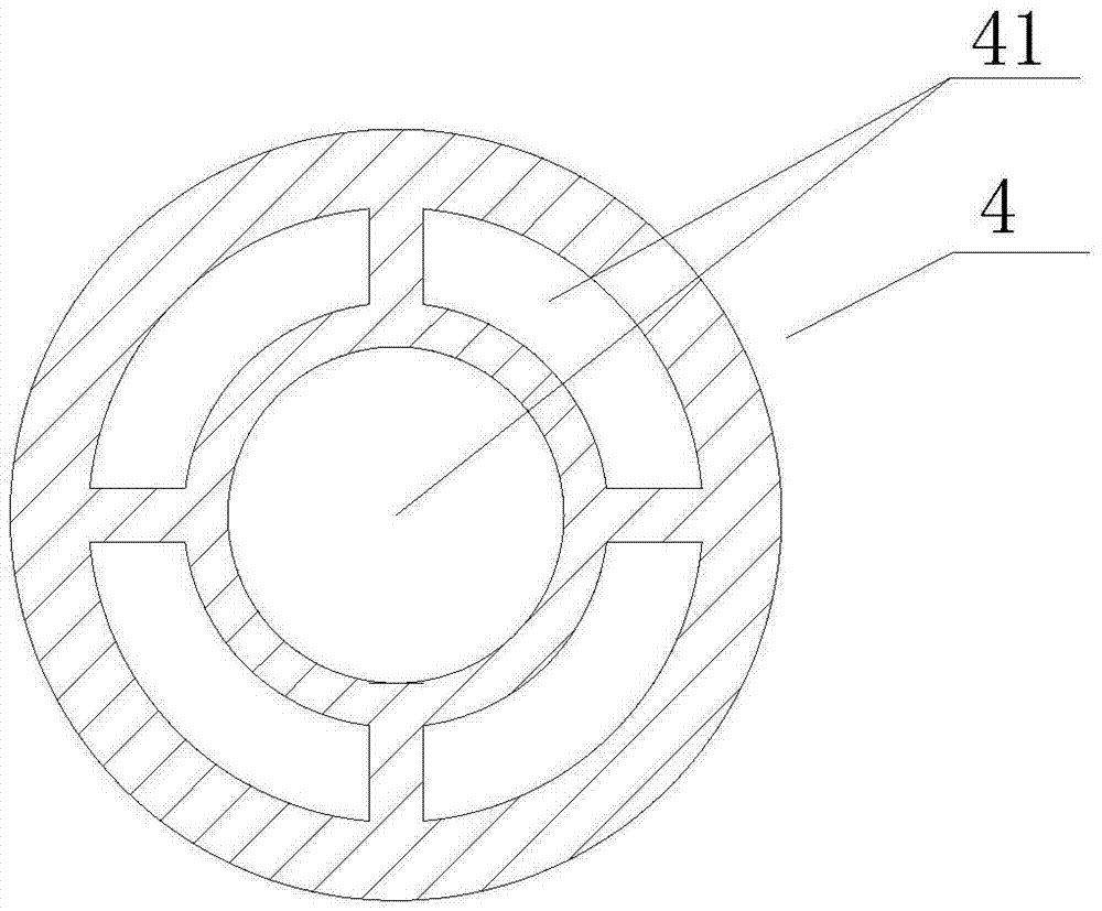
[0019] Such as Figure 1-2 as shown, figure 1 It is a structural schematic diagram of an engine water cooling device proposed by the present invention; figure 2 It is a structural schematic diagram of the heat conduction sheet in an engine water cooling device proposed by the present invention.

[0020] refer to Figure 1-2 , a water cooling device for an engine proposed by an embodiment of the present invention, comprising: a cooling main body 1, a cooling fin 2 and a radiator 3, the cooling main body 1 is made of a heat-conducting material, and the cooling main body 1 is provided with a housing cavity 11, which is used The housing cavity 11 fixes the engine in the cooling body 1; the outer peripheral surface of the cooling body 1 is provided with a plurality of annular slots arranged at intervals along the axial direction of the housing cavity 11; one si...


PUM


Abstract

The invention discloses a water cooling device for an engine, comprising: a cooling main body, a cooling fin and a radiator, the cooling main body is provided with an accommodation cavity for placing the engine; the outer peripheral surface of the cooling main body is provided with a plurality of The annular slots arranged at intervals in the line direction; one side of the heat sink is inserted into the annular slot; the cooling body is located on the outer periphery of the housing cavity, and the first flow channel and the second flow channel are arranged in sequence from the side close to the housing cavity to the side away from the housing cavity. Two flow channels; the first flow channel and the second flow channel are respectively provided with a liquid inlet and a liquid outlet, and the liquid inlet of the first flow channel is connected with the outlet of the radiator, and the liquid outlet of the first flow channel is connected with the second flow channel The liquid inlet of the channel is connected; the liquid outlet of the second channel is connected with the inlet of the radiator, and a plurality of heat conduction fins are arranged at intervals along the flow direction of the medium in the second flow channel, and each heat conduction fin is provided with a channel for the medium to pass through. hole. The invention has simple structure and fast heat dissipation speed for the cooling liquid after absorbing heat.

Description

technical field [0001] The invention relates to the technical field of automobiles, in particular to an engine water cooling device. Background technique [0002] At present, as the main means of transportation for families, cars are gradually replacing other means of transportation, resulting in an increasing frequency of daily use. More and more car owners choose to travel or go on a business trip by car to drive the car for a long distance, which will cause the car engine to overheat, which may easily cause problems such as boiling of the coolant and excessive engine temperature. In this case, the car owner needs to stop and wait Continue driving after the engine cools down, which will cause damage if the owner is in an emergency. [0003] At present, in the cars on the market, the cooling of the engine is mainly carried out by the water cooling system. This system circulates the coolant in the engine cooling system to take away the excess heat generated by the engine so...

Claims


Application Information

Patent Timeline
Patent Type & Authority Applications(China)
IPC IPC(8): F01P3/12
CPCF01P3/12
Inventor 郑志勋
Owner WUHU YONGYU AUTOCAR INDAL
Learn More