Pneumatic cylinder for controlling valve rod

A technology for controlling valves and pneumatic cylinders, which is applied to valve operation/release devices, cylinders, valve details, etc., can solve the problems of complex changes in control valve torque, insufficient linearity of valve opening and closing, and complex control mechanisms, and achieves simple structure, The effect of energy saving and high reliability

Inactive Publication Date: 2017-06-16
王翔
View PDF6 Cites 3 Cited by
  • Summary
  • Abstract
  • Description
  • Claims
  • Application Information

AI Technical Summary

Problems solved by technology

[0005] In the control of the valve, the pneumatic control valve is a convenient, reliable and environmentally friendly pneumatic control mechanism, but most of the existing valve pneumatic control uses two pneumatic cylinders, which makes the control mechanism of the valve more complicated, and the piston in the pneumatic cylinder The rod can only run in a straight line, so that the opening and closing of the valve is not linear enough, and the torque change of the control valve is more complicated

Method used


Image

  • Pneumatic cylinder for controlling valve rod

Examples


Embodiment Construction

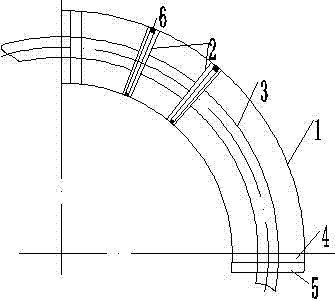
[0019] The present invention will be described in detail below in conjunction with the accompanying drawings.

[0020] Such as figure 1 A pneumatic cylinder for controlling the valve stem is shown, the pneumatic cylinder for controlling the valve stem includes: a cylinder body 1, a piston 2, a piston rod 3, a cylinder head 4, a dust cover 5, and a piston seal 6, The piston 2 is installed in the cylinder body 1, the two ends of the cylinder body 1 are equipped with a cylinder head 4, the piston 2 is provided with two piston rods, and the center of an end surface of the two piston rods passes through the connecting rod The two piston rods are respectively equipped with piston rods 3 at the centers of the other end faces of the two piston rods, and the two piston rods 3 pass through the cylinder heads 4 installed at both ends of the cylinder body 1 respectively, and the end faces of the cylinder head 4 An air intake nozzle and an exhaust nozzle are provided, and a dustproof cove...


PUM


Abstract

The invention discloses a pneumatic cylinder for controlling a valve rod. A piston is installed in a cylinder body, cylinder covers are installed at the two ends of the cylinder body, the piston is provided with two piston columns, the circle centers of one end faces of the two piston columns are connected through a connecting rod, the circle centers of the other end faces of the two piston columns are provided with piston rods respectively, the two piston rods penetrate through the cylinder covers at the two ends of the cylinder body respectively, and air inflow nozzles and air exhaust nozzles are arranged on the end faces of the cylinder covers. Dustproof covers are installed outside the cylinder covers, the dustproof covers are installed on the cylinder body, and the center liens of the cylinder body, the piston and the piston rods are arc lines. The pneumatic cylinder for controlling the valve rod is simple in structure, more reliable, small in size and convenient to install, and is provided with one cylinder body and the double piston rods, and by means of the pneumatic cylinder, more energy is saved, and more manufacturing cost is reduced.

Description

technical field [0001] The invention relates to the field of valves, in particular to a pneumatic cylinder for controlling a valve stem. Background technique [0002] The valve is a control component in the fluid delivery system, which has functions such as cut-off, adjustment, flow diversion, reverse flow prevention, pressure stabilization, flow diversion or overflow pressure relief. [0003] Valves used in fluid control systems range from the simplest cut-off valves to various valves used in extremely complex automatic control systems, with a wide variety of varieties and specifications. Valves can be used to control the flow of various types of fluids such as air, water, steam, various corrosive media, mud, oil, liquid metal and radioactive media. [0004] The control of the valve can adopt a variety of transmission methods, such as manual, electric, hydraulic, pneumatic, turbine, electromagnetic, electro-hydraulic, electro-hydraulic, gas-hydraulic, spur gear, bevel gear...

Claims


Application Information

Patent Timeline
Patent Type & Authority Applications(China)
IPC IPC(8): F16K31/122F15B15/12F15B15/20F16J10/02F16J1/12F16J7/00
CPCF16K31/1225F15B15/125F15B15/20
Inventor 王翔
Owner 王翔
Why Eureka
Try Eureka