
A kind of pollinator suitable for high-branch pollination

A technology of pollinators and high branches, which is applied in the fields of application, plant genetic improvement, agriculture, etc., can solve the problems of unsecured pollination rate, difficult pollen spraying, and difficult climbing operation, etc., and achieves improved pollination efficiency and light weight. , the effect of easy operation

Active Publication Date: 2020-04-03
钱敬乐
View PDF5 Cites 0 Cited by
  • Summary
  • Abstract
  • Description
  • Claims
  • Application Information

AI Technical Summary

Problems solved by technology

[0002] In traditional agricultural production, when the crops grow to bloom, the pollen of the stamens of the male plants needs to fall on the female plants with the help of natural wind force or carried by insects, so as to complete the pollination. impact, the pollination rate cannot be guaranteed. In order to increase the pollination rate, the method of manual pollination is usually used. Although this method has a high pollination rate, it is slow and labor-intensive. It is relatively high for large trees, especially for pear trees. Trees with high flower blooms need to climb trees for artificial pollination, which increases the difficulty of pollination; the existing pollinators are all operated with short handles, resulting in too small airflow, it is not easy to spray pollen, and it is easy to spray pollen when the airflow is too large. Disperse the pollen, affect the pollination rate, and it is not easy to climb high, so a device suitable for high-branch pollination is needed

Method used


Image

  • A kind of pollinator suitable for high-branch pollination
  • A kind of pollinator suitable for high-branch pollination
  • A kind of pollinator suitable for high-branch pollination

Examples


Embodiment Construction

[0026] The present invention will be further described below in conjunction with the accompanying drawings.

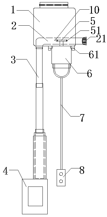
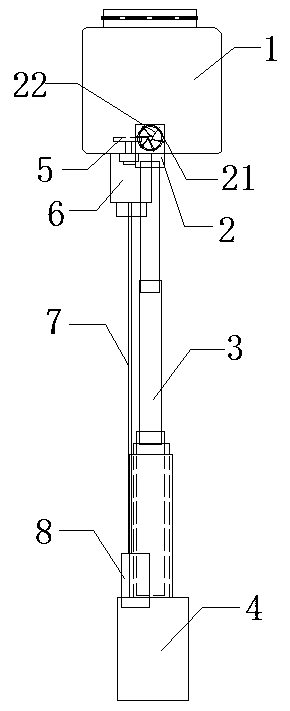
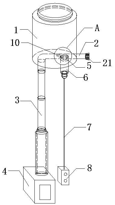
[0027] Such as Figure 1-5 As shown in , a pollinator suitable for high-branch pollination includes a powder storage tank 1, and the powder storage tank 1 is provided with an L-shaped tube 2 that runs through the bottom surface and the side of the powder storage tank 1, and the bottom of the L-shaped tube 2 communicates with a telescopic The airflow lifting rod 3 is connected with the electric blower 4 below the airflow lifting rod 3; the L-shaped pipe 2 side is provided with an air spout 21, where the air spout is a trumpet shape opened outwards, and the L-shaped pipe 2 wall side is provided with a rectangular cavity The slot 23 is provided with a horizontally arranged wheel piece 5 at the rectangular empty slot 23, the bottom of the wheel piece 5 is driven by a motor 6 located at the bottom of the powder storage tank 1, and one side of the wheel piece 5 is arranged i...


PUM


Abstract

The invention belongs to the technical field of mechanical pollination, in particular to a pollinator suitable for high branch pollination. The pollinator includes a powder storage tank, wherein an L-shaped tube runs through the bottom surface and the side surface of the powder storage tank, the bottom of the L-shaped tube communicates with a telescopic airflow lifting rod, and the lower part of the airflow lifting rod is connected with an electric blower; and an air injection port is located on one side of the L-shaped tube, and a rectangular hollow groove is located on one side of the L-shaped tube wall, and a wheel plate is horizontally installed at a position where the rectangular hollow groove is located. Compared with the prior art, the pollinator has the following advantages: the airflow lifting rod buffers the wind speed of the electric blower to a certain extent, the operable space of the pollinator is expanded as well, the length of the airflow lifting rod is adjusted according to the height of the flowers to be pollinated, the pollinator is turned on above the flowers to be pollinated, and pollens are blown out evenly and can fall on female plants stably; and the wheel plate can continuously carry a small amount of pollens into the L-shaped tube, thereby the coefficient of utilization of pollens is improved and waste of pollens caused by being blown out in large amount is avoided.

Description

technical field [0001] The invention belongs to the technical field of mechanical pollination, and in particular relates to a pollinator suitable for high branch pollination. Background technique [0002] In traditional agricultural production, when the crops grow to bloom, the pollen of the stamens of the male plants needs to fall on the female plants with the help of natural wind force or carried by insects, so as to complete the pollination. impact, the pollination rate cannot be guaranteed. In order to increase the pollination rate, the method of manual pollination is usually used. Although this method has a high pollination rate, it is slow and labor-intensive. It is relatively high for large trees, especially for pear trees. Trees with high flower blooms need to climb trees for artificial pollination, which increases the difficulty of pollination; the existing pollinators are all operated with short handles, resulting in too small airflow, it is not easy to spray polle...

Claims


Application Information

Patent Timeline
Patent Type & Authority Patents(China)
IPC IPC(8): A01H1/02
CPCA01H1/027
Inventor 钱敬乐周尽忠
Owner 钱敬乐
Learn More