Gas-liquid separation device with built-in heat exchanger, and gas-liquid separation method

A gas-liquid separation device and technology for gas-liquid separation, which are applied in separation methods, chemical instruments and methods, and dispersed particle separation, etc., can solve the problems of high production cost, only separation of gas and water, and no cooling function, etc. To achieve the effect of low manufacturing and use costs, good separation and cooling effects, and conducive to popularization and application

Inactive Publication Date: 2017-06-20
WUHAN WU PUMP PUMP MFG
View PDF10 Cites 11 Cited by
  • Summary
  • Abstract
  • Description
  • Claims
  • Application Information

AI Technical Summary

Problems solved by technology

However, it is difficult to maintain in actual operation, especially in long-term operation, the temperature of the working water will rise above 50°C, resulting in the deterioration of the pumping efficiency of the vacuum pump. When the temperature is higher, the vacuum pump even loses the pumping function, which directly affects The working performance of the vacuum pump and the safe operation of the system, while the traditional gas-water separator can only separate the gas and water, does not have the cooling function, the cooling of the working water depends on an independent heat exchanger, while the current heat exchanger cooling The effect is poor, it is difficult to meet the requirements of the working water temperature of the vacuum pump, and the resistance of the heat exchanger is large, which increases the water inlet resistance of the vacuum pump, resulting in an increase in power consumption of the vacuum pump and a decrease in pumping efficiency
At present, the gas-water separator with built-in heat exchanger commonly used, such as the gas-water separator described in the above-mentioned patent, cannot be effectively compatible because of its production cost, separation liquid temperature, gas content, and operation stability, resulting in High production costs, frequent maintenance, low work efficiency, easy to generate gas turbidity, short service life of vacuum pumps, etc.

Method used


Image

  • Gas-liquid separation device with built-in heat exchanger, and gas-liquid separation method
  • Gas-liquid separation device with built-in heat exchanger, and gas-liquid separation method
  • Gas-liquid separation device with built-in heat exchanger, and gas-liquid separation method

Examples


Embodiment Construction

[0044] In the following, the present invention will be described in detail and specifically through specific examples, so as to better understand the present invention, but the following examples do not limit the scope of the present invention.

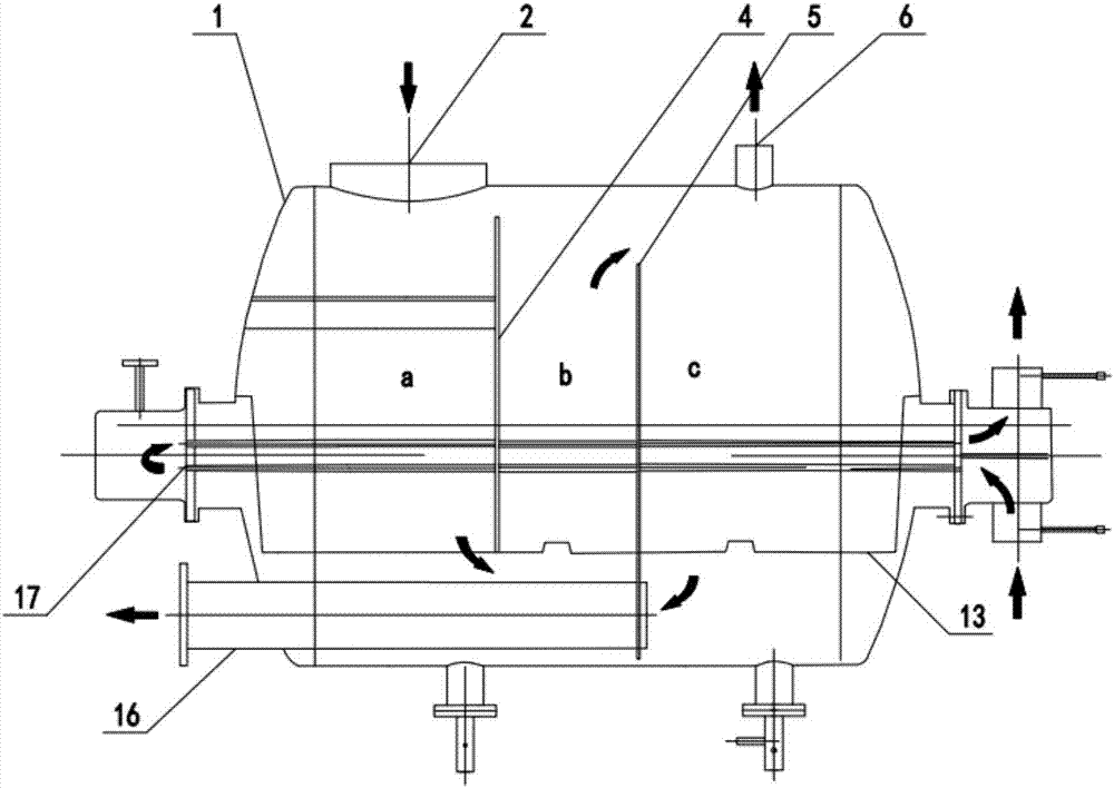
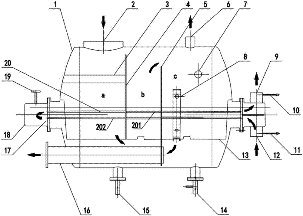
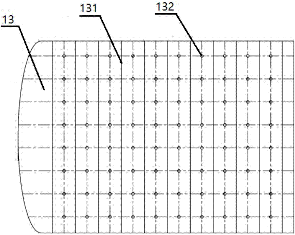
[0045] Such as figure 1 As shown, the present invention provides a gas-liquid separation device with a built-in heat exchanger, including a housing 1, the top of the housing 1 is provided with a gas-liquid mixture inlet 2, and an air outlet 6, wherein: inside the housing 1, there are horizontally arranged The tubular heat exchanger 17 that runs through the left and right side walls of the housing 1 is used to exchange heat for the gas-liquid mixture entering the housing 1. The lower part of the tubular heat exchanger 17 is connected to the The area between the bottom of the housing 1 is also provided with a deceleration orifice plate 13 laterally, which is used to reduce the gas-liquid mixture liquid passing through the deceleration o...


PUM


Abstract

The invention discloses a gas-liquid separation device with a built-in heat exchanger. The device comprises a shell, the tubular heat exchanger is transversely arranged in the shell, and a deceleration pore plate is arranged at the lower portion of the tubular heat exchanger; and an upper baffle plate and a lower baffle plate are vertically arranged in the shell, the tubular heat exchanger penetrates through the upper baffle plate and the lower baffle plate, the upper baffle plate and the lower baffle plate sequentially divide the internal of the shell into a first separation and heat exchange area, a second separation and heat exchange area and a heat exchange and water collection area, a gas-liquid mixture sequentially goes through first separation and heat exchange area, the second separation and heat exchange area and the heat exchange and water collection area, respectively undergoes heat exchange and gas-liquid separation, and is discharged from a water outlet tube. The invention also provides a gas-liquid recovery method based on the gas-liquid separation device with the built-in heat exchanger, and a water return system of a vacuum set. The gas-liquid separation device has gas-liquid separation and heat exchange functions, and also has the advantages of small resistance, compact structure, good separating and cooling effect, low manufacturing and use cost, and facilitation of promotion and use.

Description

technical field [0001] The invention relates to a gas-liquid separation device in the fields of chemical industry, pharmacy, food, machinery, exploration, electric power, electronic production, etc., in particular to a gas-liquid separation device with a built-in heat exchanger and a gas-liquid separation method thereof, especially to a gas-liquid separation device using The return water system of the vacuum pump unit of the gas-liquid separation device with built-in heat exchanger. Background technique [0002] In chemical, pharmaceutical, food, machinery, exploration, electric power, electronic production and other engineering fields, vacuum pumps are widely used to form a vacuum or pressure in a closed container or system, and part of the gas-liquid mixture is separated by a gas-liquid separator. The product needs to be refluxed and recycled. For example, in the liquid ring vacuum pump system, the separated liquid and liquid phase separation product can only enter the vac...

Claims


Application Information

Patent Timeline
Patent Type & Authority Applications(China)
IPC IPC(8): B01D45/04B01D45/08B01D45/06B01D19/00
CPCB01D19/0068B01D45/04B01D45/06B01D45/08
Inventor 张怀明
Owner WUHAN WU PUMP PUMP MFG
Why Eureka
Try Eureka