Method for producing truck push rod support through iron mold sand coating casing

A technology of sand-covered iron casting and production methods, which is applied to casting molding equipment, casting molds, cores, etc., can solve problems such as poor surface quality, unguaranteed overall mechanical properties, and loose organization, and achieve low manufacturing costs , Eliminate the defects of subcutaneous stomata, the effect of short production cycle

Inactive Publication Date: 2017-06-20
GUANGXI YUCHAI MACHINE PARTS MFG CO LTD
6 Cites 1 Cited by

AI-Extracted Technical Summary

Problems solved by technology

[0006] The technical problem to be solved by the present invention is to provide a production method of iron mold sand-coated casting truck push rod brackets, which solves the common problems ...

Method used

Iron mold sand-covered casting technique of the present invention is to utilize iron mold to increase the cooling rate of molten iron in casting process, refines structure, has improved truck push rod support and guaranteed body thicker part or thicker under the uneven wall thickness situation Tissue compactness of bosses and towers. Under...

Abstract

The invention discloses a method for producing a truck push rod support through iron mold sand coating casting. An inner cavity of an iron mold is manufactured according to the shape of the truck push rod support in a following manner, the thickness of a following sand coating layer ranges from 7 mm to 8 mm, and a closed sprue is adopted; air hole needles are arranged on a jet hole in the highest position and peripheral core heads of an upper half die sample, and an exhaust groove is formed in a parting face of the iron mold; heating devices are arranged in the middle of an upper die bottom plate and the middle of a lower die bottom plate of an outer die correspondingly, and sand jetting is conducted after the temperature reaches the requirement; and core loading, box closing, casting and box opening are conducted after a sand core is manufactured. By the adoption of the method, the yield is increased to 83% or higher of iron mold casting from 65% of original sand mold casting, the defects of subskin porosity, organization looseness and the like are overcome, the problem of cracking of the truck push rod support during work is solved, the overall mechanical performance is improved, sand treatment equipment, fields and the sand use amount are reduced, and the severe casting environment is improved; and the technological processes are simple, control is easy, and the production cost is lowered than that of sand mold casting by 30%-50%.

Application Domain

Foundry mouldsFoundry cores +1

Technology Topic

TruckPorosity +3

Image

  • Method for producing truck push rod support through iron mold sand coating casing
  • Method for producing truck push rod support through iron mold sand coating casing

Examples

  • Experimental program(1)

Example Embodiment

[0027] The specific embodiments of the present invention are described in detail below, but do not constitute a limitation to the protection scope of the claims of the present invention.
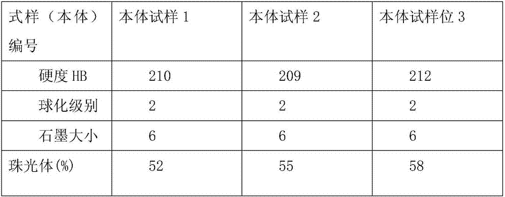
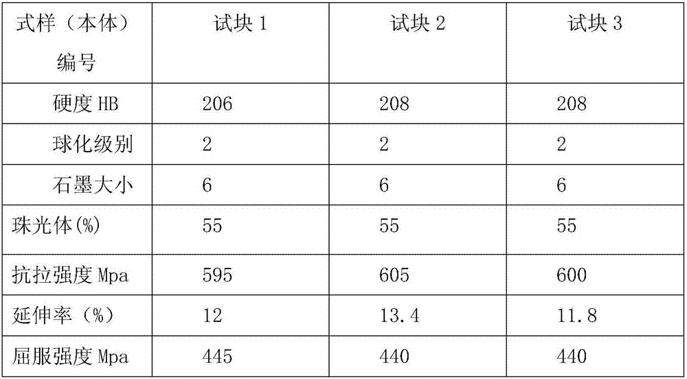
[0028] The iron mold sand-coated casting process of the present invention uses the iron mold to increase the cooling rate of the molten iron in the casting process, refine the structure, and improve the truck push rod bracket to ensure that the thicker part or thicker boss, The tightness of the structure of the tower. Under the same composition of molten iron, using iron sand-coated casting process to produce the machine body can obtain higher tensile strength, hardness and better graphite morphology and graphite size level than sand casting process, and stabilize pearlite at more than 50%. The most important thing is to improve the elongation of the truck push rod bracket.
[0029] The difference between the iron sand coating casting process of the truck push rod bracket of the present invention and the static pressure sand casting process is in the molding process. The iron sand coating casting process of the truck push rod bracket of the present invention uses a special ZXTF-Z-1350* 740 model host automatic production line. According to the requirements of the iron type specification, the truck push rod bracket is designed and arranged into 8 pieces/type, divided into upper and lower molds. The rated productivity of the production line is 15 types/h, and the two molding hosts are 30 types/h. The sand box is a metal type, the inner cavity is according to the shape of the truck push rod bracket, leaving the thickness of the sand layer and being molded. A heating device is provided under the bottom of the outer mold. The mold temperature and the iron mold temperature are both thermostatically controlled at 180 -240°C. The molding adopts coated sand. When the temperature of the mold and the iron mold reaches the set temperature, a thin layer of molding sand is covered around the inner cavity of the iron mold.
[0030] Since the coated sand is fluid and dry, it has no moisture. After the surface is hardened by the sand shot, the surface finish is very good. No coating is required. The static pressure sand casting process is wet (tidal) casting, and the surface needs to be coated Coating can guarantee the smoothness of castings. Therefore, the iron mold sand-coated casting process can save a lot of coating costs.
[0031] Taking the production of the Liuzhou Wuling truck push rod bracket as an example, when the static pressure casting production process is used, the amount of sand used for modeling is more than 622kg, and when the iron mold sand coating process is used to produce the truck push rod bracket (8 pieces/model), the casting The amount of sand used for a single modeling machine is only about 18-20kg; if the cost is calculated at the current price, the annual output of 200,000 pieces of light modeling sand can save more than 800,000 yuan. And the iron mold sand-coated casting production line of this scale reduces the investment by 15 million yuan compared with the domestic static pressure production line, and reduces the investment by more than 20 million yuan than the imported static pressure production line.
[0032] The iron-type sand-coated casting process of the truck push rod bracket of the present invention has the advantages of high process yield, compact structure and no leakage, high comprehensive performance, low sand consumption, low equipment investment, short production cycle, quick effect, and small equipment occupation area. While it has the advantages of high production efficiency, low manufacturing cost, and good environmental protection, its shortcomings are that various iron sand boxes have no versatility and the single-day output is low due to the influence of equipment.
[0033] Using the method of the present invention to produce 9002778 Liuzhou Wuling truck push rod bracket, the specific process steps are as follows:
[0034] 1. Modeling
[0035] The appearance is made by iron sand-coated casting process. The outer sand box is made of iron type, and the coated sand is made of phase change sand, that is, the old sand is recovered and processed and then re-coated. The iron mold casting process is designed according to 8 pieces/type, and the inner cavity of the iron mold is based on the truck push rod bracket The shape is made according to the mould, and the thickness of the sand layer is 8mm during trial production. The molten iron runner of the pouring system is from the sprue cup to the straight runner to the horizontal runner, and then from the horizontal runner through the filter screen and then evenly distributed to the inner gate to the casting; the pouring system adopts a closed gate, and each gate The ratio of the total cross-section is: ∑ Straight: ∑ Horizontal: ∑ Inner = 1: (0.75-0.78): (0.68-0.72); the filter screen adopts straight hole ceramic filter screen. In order to overcome the shortcomings of the iron type process and the exhaust problem, the perforation at the highest point of the upper mold pattern is equipped with pore needles with an outer diameter of Φ8mm, and the surrounding cores of the upper mold are equipped with pore needles with an outer diameter of Φ10mm, and they do not penetrate. Box surface: Semicircular exhaust grooves with a diameter of Φ6mm are evenly distributed on the parting surface of the iron type. The upper and lower mold bottom plates of the outer mold are equipped with heating devices respectively, and the mold temperature and the temperature of the iron mold are controlled at 180-240℃; when the temperature reaches the process requirements, the sand is shot, the sand shot pressure is 0.35-0.40Mpa, and the curing time is 50-60S, the color of the sand coating after sand shooting is controlled to brown. In continuous production, the cast iron mold must be water-cooled to meet the temperature control requirements before it can be recycled (the temperature is measured by infrared rays).
[0036] 2. Sand core
[0037] Direct injection with mould hanging core method;
[0038] 3. Close the box
[0039] Check the quality of the mold before the box to ensure that the mold meets the requirements and blow the mold clean with compressed air; then use 6mm sealing strips to surround the positioning pins of the sand box, install a filter on the gating system filter seat, and blow on the box After cleaning, close the box and buckle the box. The box closing force is 80-85N.M. The sprue cup adopts a disposable ceramic straight-flush funnel sprue cup. When it is installed on the iron mold, apply a layer of special casting viscose to the contact surface to stick it firmly, and put a pressure iron on the sprue cup to wait for pouring.
[0040] 4. Pouring
[0041] Use QT600-10 grade molten iron for pouring, and its chemical composition mass ratio is:
[0042] C: 3.7~3.9%, Si: 1.6~1.7%, Mn≤0.2%, Cu≤0.2%, Re: 0.01%~0.02%, Mg: 0.03%~0.05%;
[0043] The pouring temperature is controlled at 1420℃-1440℃, and the pouring time (8 pieces/type) is 9.5-10.5s; the pouring cup is interrupted when the molten iron in the pouring cup becomes a paste;
[0044] 5. Unpacking
[0045] Open the box 25 minutes after pouring; drop the box when the solidification time of the casting is 35 minutes, the casting after the box drop is dark red, and then freely cool to room temperature.
[0046] 6. Inspection results
[0047] After the casting is cleaned and shot blasted, without heat treatment, the directly as-cast dissected casting inspection results are as follows:
[0048] 1) The metallographic structure and hardness of each part of the truck push rod bracket are as follows:
[0049]
[0050] 2) Mechanical properties
[0051] The performance test is attached with a casting test block, the details are as follows:
[0052]
[0053] Using the iron mold sand coating method of the present invention to cast the truck push rod bracket can reduce or eliminate the addition of alloys under the condition of meeting the performance requirements. For example, the Cu alloy can be reduced from the original 0.7-0.8% to 0.2-0.3%.
[0054] Practical description: the use of the method of the present invention to produce truck push rod brackets has a body mechanical performance that is more than one grade higher than the required grade of sand casting body, thereby ensuring that it meets the competition requirements of the growing automobile manufacturing industry.
[0055] With the method of the present invention, not only can the compacted graphite cast iron or ductile cast iron auto parts, cylinder blocks, cylinder heads, exhaust pipes and other high-quality important automobile parts be produced, but also can be used in machinery manufacturing in various industries, such as Aviation, railway rolling stock, agricultural machinery, construction machinery and military industry, etc. need to withstand the production of large, medium and small parts with high strength, high toughness, high density, and high wear resistance.

PUM

PropertyMeasurementUnit
Thickness10.0 ~ 30.0mm

Description & Claims & Application Information

We can also present the details of the Description, Claims and Application information to help users get a comprehensive understanding of the technical details of the patent, such as background art, summary of invention, brief description of drawings, description of embodiments, and other original content. On the other hand, users can also determine the specific scope of protection of the technology through the list of claims; as well as understand the changes in the life cycle of the technology with the presentation of the patent timeline. Login to view more.

Similar technology patents

Heat-insulation water-control degradable mulch preparation method

ActiveCN107254150AImprove degradation rateImprove overall mechanical properties
Owner:成都硕谷农业科技有限公司

Low-temperature plug valve

ActiveCN103994246AStrength and rigidity meetImprove overall mechanical properties
Owner:施瑞德阀门(厦门)有限公司

Smelting additive specially used for cast balls and wear-resistant cast iron

InactiveCN102732775AImprove overall mechanical propertiesExtended service life
Owner:CHAOYANG HONGDA MACHINERY

Aluminum magnesium alloy containing rare earth element lanthanum and preparing method

InactiveCN107723528AReduced hot cracking tendencyImprove overall mechanical properties
Owner:YANGZHONG YANGZILV PROCESSING CO LTD

Aluminum alloy grain refiner and preparation method thereof

InactiveCN105543524AImprove overall mechanical propertiesThe process is simple and reasonable
Owner:HUAZHONG UNIV OF SCI & TECH
Why Eureka
Try Eureka