Supercharge Your Innovation With Domain-Expert AI Agents!

Automatic pipe cutting machine

A pipe cutting machine, automatic technology, applied in the direction of pipe shearing device, shearing device, accessories of shearing machine, etc., to achieve the effect of reducing production links, simple structure and improving production efficiency

Inactive Publication Date: 2017-06-20
GUANGXI CHUNMAO INVESTMENT CO LTD
View PDF11 Cites 0 Cited by
  • Summary
  • Abstract
  • Description
  • Claims
  • Application Information

AI Technical Summary

Problems solved by technology

[0003] The technical problem to be solved by the present invention is: to provide an automatic pipe cutting machine, which can automatically feed materials, and solve the technical problem that the pipe cutting machine produces edging during the cutting process

Method used


Image

  • Automatic pipe cutting machine
  • Automatic pipe cutting machine
  • Automatic pipe cutting machine

Examples


Embodiment Construction

[0025] The present invention will be further described below in conjunction with the accompanying drawings and embodiments.

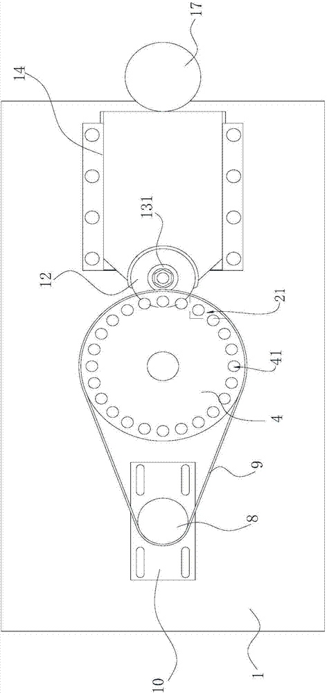
[0026] combine figure 1 and figure 2 Commonly shown, an automatic pipe cutting machine includes a frame 1, and the driving device includes a first driving motor 16 and a second driving motor 17, and the first driving motor 16 and the second driving motor 17 are respectively fixedly installed on the frame 1.

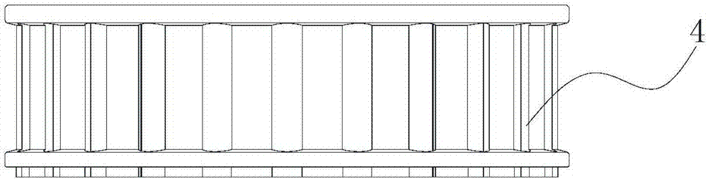
[0027] The feeding device includes a first transmission shaft 3 and a wheel seat 2 fixedly installed on the frame 1, the first transmission shaft 3 runs through the wheel seat 2, and the lower end of the first transmission shaft 3 is connected to the first driving motor 16 in transmission, and the wheel Above the top surface of the disk seat 2, the first transmission shaft 3 is fixedly sleeved with a feed wheel 4 and a feed wheel gasket 5, and the feed wheel gasket 5 is located below the feed wheel 4, and the feed wheel An annular knife groove 7...


PUM


Abstract

The invention discloses an automatic pipe cutting machine which comprises a machine frame. A first transmission shaft penetrates through a wheel disc base. The lower end of the first transmission shaft is in transmission connection with a driving device. The first transmission shaft is fixedly sleeved with a feeding wheel disc and a feeding wheel disc gasket located above the top face of the wheel disc base. The feeding wheel disc is provided with a plurality of vertically cut-through feeding round holes. Each feeding round hole completely or locally penetrates through a wheel groove. Pipe material stop openings with the number corresponding to the number of the feeding round holes are formed in the periphery of the feeding wheel disc gasket. The pipe material stop openings are half-round gaps. One side of the feeding wheel disc is provided with a driven belt wheel. The feeding wheel disc and the driven belt wheel are in transmission connection through a pressing belt. A pipe cutting device comprises a round blade arranged in an annular tool slot. The round blade is fixedly installed on a second transmission shaft which is in transmission connection with the driving device. According to the automatic pipe cutting machine, automatic feeding can be achieved, and the technical problem that burrs are produced in the cutting process of the pipe cutting machine is solved.

Description

technical field [0001] The invention relates to the technical field of pipe processing equipment, in particular to an automatic pipe cutting machine. Background technique [0002] In recent years, due to people's increasing demand for poultry, the scale of poultry farming is also expanding. In the process of poultry farming, most companies will mark their own brand logos on poultry, and the more commonly used marking method is to put copper rings with brand logos on the feet of poultry shortly after birth. Because of the good ductility of the copper material, it is easy to produce ridges in the process of cutting the bobbin, but the existing pipe cutting equipment on the market cannot solve this problem, so a lot of manual work is required to remove the ridges, which reduces the production efficiency. Low, greatly increasing the production cost. Contents of the invention [0003] The technical problem to be solved by the present invention is to provide an automatic pipe ...

Claims


Application Information

Patent Timeline
Patent Type & Authority Applications(China)
IPC IPC(8): B23D19/00B23D21/00B23D33/02
CPCB23D19/00B23D21/00B23D33/02
Inventor 卢辉文德贤谭启寅陈国联
Owner GUANGXI CHUNMAO INVESTMENT CO LTD
Features
  • R&D
  • Intellectual Property
  • Life Sciences
  • Materials
  • Tech Scout
  • Unparalleled Data Quality
  • Higher Quality Content
  • 60% Fewer Hallucinations
Learn More