Quick welding equipment for special metal parts for industry

A technology for metal parts and welding equipment, which is applied in the field of fast welding equipment for industrial special metal parts, and can solve the problems of insufficient welding position accuracy and time-consuming and laborious welding process.

Inactive Publication Date: 2017-06-20
邝德安
View PDF7 Cites 12 Cited by
  • Summary
  • Abstract
  • Description
  • Claims
  • Application Information

AI Technical Summary

Problems solved by technology

[0008] In order to overcome the shortcomings of insufficient welding position accuracy and time-consuming and labor-intensive welding process when welding irregular metal parts, the technical prob

Method used


Image

  • Quick welding equipment for special metal parts for industry
  • Quick welding equipment for special metal parts for industry
  • Quick welding equipment for special metal parts for industry

Examples


Embodiment 1

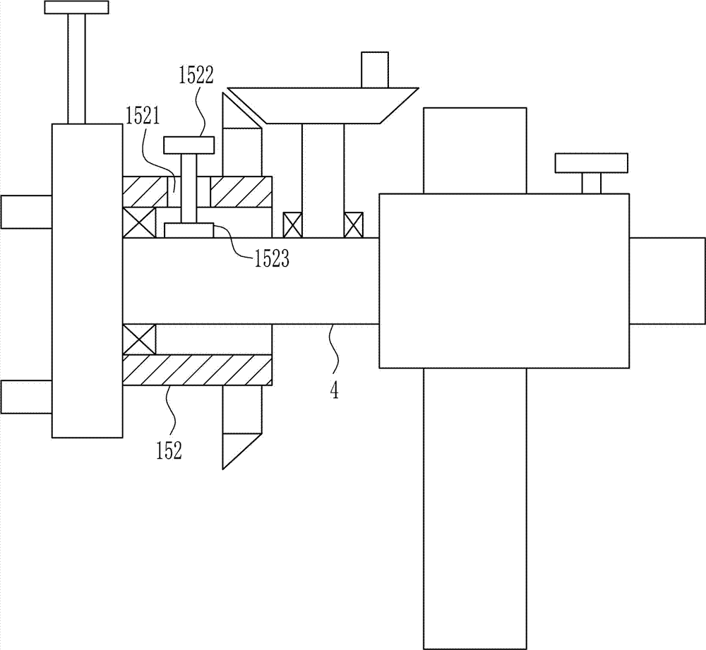
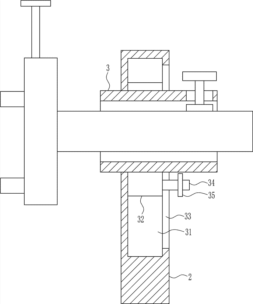
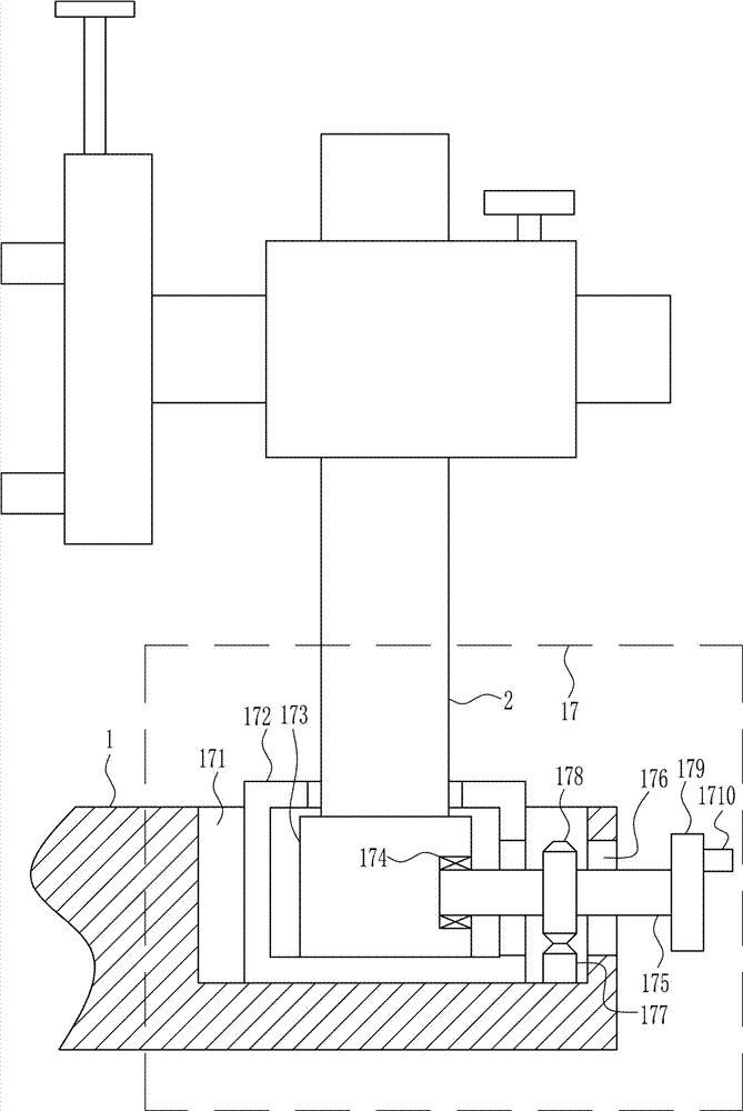
[0039] A fast welding equipment for industrial special metal parts, such as Figure 1-8 As shown, it includes a bottom plate 1, a support plate 2, a guide sleeve 3, a guide rail 4, a first screw rod 6, a first pressure block 7, a fixed plate 8, a placement block 9, a first slide rail 10, a first slide block 11, The pressure plate 12 and the second screw rod 14, the left and right sides of the bottom plate 1 are installed with a support plate 2 by welding, the upper front side of the support plate 2 is installed with a guide sleeve 3 by welding, and the guide sleeve 3 is slidingly connected with a guide rail 4 The outer side of the guide rail 4 is provided with a first threaded hole 5, the first threaded hole 5 is internally screwed with a first screw 6, the first screw 6 cooperates with the first threaded hole 5, and the lower end of the first screw 6 is rotatably connected with a first pressure block 7. A fixing plate 8 is installed on the inner side of the guide rail 4 by we...

Embodiment 2

[0041] A fast welding equipment for industrial special metal parts, such as Figure 1-8 As shown, it includes a bottom plate 1, a support plate 2, a guide sleeve 3, a guide rail 4, a first screw rod 6, a first pressure block 7, a fixed plate 8, a placement block 9, a first slide rail 10, a first slide block 11, The pressure plate 12 and the second screw rod 14, the left and right sides of the bottom plate 1 are installed with a support plate 2 by welding, the upper front side of the support plate 2 is installed with a guide sleeve 3 by welding, and the guide sleeve 3 is slidingly connected with a guide rail 4 The outer side of the guide rail 4 is provided with a first threaded hole 5, the first threaded hole 5 is internally screwed with a first screw 6, the first screw 6 cooperates with the first threaded hole 5, and the lower end of the first screw 6 is rotatably connected with a first pressure block 7. A fixing plate 8 is installed on the inner side of the guide rail 4 by we...

Embodiment 3

[0044] A fast welding equipment for industrial special metal parts, such as Figure 1-8 As shown, it includes a bottom plate 1, a support plate 2, a guide sleeve 3, a guide rail 4, a first screw rod 6, a first pressure block 7, a fixed plate 8, a placement block 9, a first slide rail 10, a first slide block 11, The pressure plate 12 and the second screw rod 14, the left and right sides of the bottom plate 1 are installed with a support plate 2 by welding, the upper front side of the support plate 2 is installed with a guide sleeve 3 by welding, and the guide sleeve 3 is slidingly connected with a guide rail 4 The outer side of the guide rail 4 is provided with a first threaded hole 5, the first threaded hole 5 is internally screwed with a first screw 6, the first screw 6 cooperates with the first threaded hole 5, and the lower end of the first screw 6 is rotatably connected with a first pressure block 7. A fixing plate 8 is installed on the inner side of the guide rail 4 by we...


PUM


Abstract

The invention relates to welding equipment, and particularly relates to quick welding equipment for special metal parts for industry. The invention aims to provide the quick welding equipment for the special metal parts for the industry, which has the advantages of high accuracy in welding positions, time saving and labor saving in welding. In order to solve the technical problem, the invention provides the quick welding equipment for the special metal parts for the industry. The quick welding equipment comprises a bottom plate, support plates, guide sleeves, guide rails, a first screw, a first pressing block and a fixed plate, wherein the support plates are installed on the left and right sides of the bottom plate in a welding mode, the guide sleeves are installed on the front sides of the support plates in a welding mode, the guide rails are connected to the interiors of the guide sleeves in a sliding mode, and first threaded holes are formed in the outer sides of the guide rails. The quick welding equipment has the effects of high accuracy in welding positions, time saving and labor saving in welding, and a mode of rotating around the rotary center of a first bearing seat and around a second sliding block after the metal parts are fixed is adopted.

Description

technical field [0001] The invention relates to welding equipment, in particular to a fast welding equipment for industrial special metal parts. Background technique [0002] Metal parts refer to the collective name of metal blocks, metal rods, metal tubes, etc. of various specifications and shapes made of metal materials. [0003] Materials of metal parts: steel and non-ferrous metals (or non-ferrous metals). Iron and steel: The alloy of iron with a carbon content of 2% to 4.3% is cast iron, and the alloy of iron with a carbon content of generally 0.03% to 2% is steel. [0004] Machining, stamping, precision casting, powder metallurgy, metal injection molding, laser processing, EDM, ultrasonic processing, electrolytic processing, particle beam processing and ultra-high speed processing, etc. Similar to turning, milling, forging, casting, grinding, CNC machining, CNC numerical control center are all conventional machining. [0005] At present, when welding irregular speci...

Claims


Application Information

Patent Timeline
IPC IPC(8): B23K37/04B23K37/047
CPCB23K37/04B23K37/047
Inventor 不公告发明人
Owner 邝德安
Why Eureka
Try Eureka