Al technical title is built by PatSnap Al team. It summarizes the technical point description of the patent document.
A jigsaw machine and wooden strip technology, which is applied in the jointing of wooden veneers, wood processing appliances, other plywood/plywood appliances, etc., can solve the problems of slow speed, easy impact, unreasonable structure, etc., and achieve high efficiency High effect with clear division of labor
Active Publication Date: 2022-05-27
PINGDINGSHAN ANTAIHUA MINING SAFETY EQUIP MFG
View PDF9 Cites 0 Cited by
Summary
Abstract
Description
Claims
Application Information
AI Technical Summary
This helps you quickly interpret patents by identifying the three key elements:
Problems solved by technology
Method used
Benefits of technology
Problems solved by technology
[0003] In order to solve the unreasonable structure of the existing wooden strip puzzle machine, the unsteady feeding, prone to sticking and accumulation of wooden strips, the speed of transportation is too slow, the noise is loud, and the wooden strips need to be manually glued in advance, which is a waste of labor and wooden When the strip reaches the end of the batten mechanism, it is easy to hit too hard, which affects the service life and other technical problems. The invention provides an automatic batten jigsaw machine to achieve reasonable structure, ingenious design, convenient blanking, stable conveying speed, and even glue coating. , with a buffer mechanism, which can be used for emergency braking and effectively prolongs the service life
Method used
Image
Click on the blue label to locate the original text in one second.
Reading with bidirectional positioning of images and text.
Examples
Embodiment Construction
[0029] The specific embodiments of the present invention will be described in further detail below with reference to the accompanying drawings.
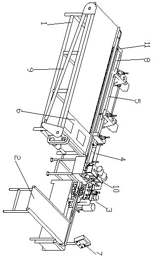
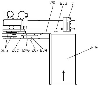
[0030]As shown in the figure, an automatic wood splicing machine includes a work frame 1, a feeding device 2 for storing wood slats, a pressure roller buffer device 3 for buffering and conveying wood slats, and a coating for gluing the sides of the wood slats. Glue device 10, sawing device for sawing the completely placed wooden strips 4, directional push and sawing wooden strips connecting device 5, push plate device for pushing away the directionally placed wooden strips 6, control panel The electrical automation control system 7 and the main conveyor belt 8 for machine operation, the feeding device 2 is arranged at the starting end of the main conveyor belt 8, and the end of the main conveyor belt 8 is provided with a retractable limit mechanism for adjusting the cutting length of the wood strips 11. The limit mechanism 11 include...
PUM
Abstract
The invention relates to an automatic wooden strip puzzle machine, which includes a working frame, a feeding device, a pressure wheel buffer device, a gluing device, a sawing device, a one-way propulsion device, a pushing board device, an electrical automation control system and a main conveyor belt , the end of the main conveyor belt is provided with a limit mechanism, and the pressure wheel buffer device includes a power mechanism, a motion mechanism and a transmission mechanism. The buffer drives the rotating shaft to move up and down through the connecting piece, and buffers the vertical displacement change of the rolling pressure wheel due to the movement. The invention has reasonable structure, ingenious design, convenient blanking, fast and stable conveying speed, integration of splicing and gluing, a buffer mechanism, effectively prolonging the service life, and solving the problem of unstable unloading of the existing wooden lath splicing machine, which is easy There are wooden sticks piled up, the speed is too slow when conveying, the noise is loud, and the wooden sticks need to be glued in advance, which wastes labor and affects the service life. Compared with the existing technology, it is a major technological innovation and has a good effect. Market prospect and development space.
Description
technical field [0001] The invention relates to a wood processing machine, in particular to an automatic wood strip assembling machine. Background technique [0002] The wood splicing machine is a commonly used machine in the wood processing industry. It is mainly used to splicing many single wood slats into a core. It is widely used in building decoration, wooden doors and other wooden furniture processing. At present, most of the wood-striping machines on the market have the following problems: First, the cutting is unstable, and the wood bars are prone to sticking and accumulation; second, the wood bars need to be manually glued in advance for backup; third, the wood bar mechanism There is no buffer device at the end, and the wooden strips reach the end of the wooden strip mechanism, and it is easy to hit too hard, resulting in gaps in the butt of the wooden strips, and even damage to the proximity switch, which affects the service life; Fourth, there is no emergency push...
Claims
Application Information
Patent Timeline
Application Date:The date an application was filed.
Publication Date:The date a patent or application was officially published.
First Publication Date:The earliest publication date of a patent with the same application number.
Issue Date:Publication date of the patent grant document.
PCT Entry Date:The Entry date of PCT National Phase.
Estimated Expiry Date:The statutory expiry date of a patent right according to the Patent Law, and it is the longest term of protection that the patent right can achieve without the termination of the patent right due to other reasons(Term extension factor has been taken into account ).
Invalid Date:Actual expiry date is based on effective date or publication date of legal transaction data of invalid patent.