3D printing sprayer

A 3D printing and nozzle technology, applied in the field of 3D printing nozzles, can solve the problems of high cost, high use and maintenance costs of photo-curing printing systems, achieve controllable curing time, avoid high costs, and solve the effect of curing after printing

Active Publication Date: 2017-06-20
ZHEJIANG UNIV
View PDF5 Cites 5 Cited by
  • Summary
  • Abstract
  • Description
  • Claims
  • Application Information

AI Technical Summary

Problems solved by technology

[0004] The purpose of the present invention is to provide a 3D printing nozzle, which overcomes the technical problems of the high cost of the photocuring printing system in the prior art and the disadvantages of high use and maintenance costs, and at the same time can realize the curing during the extrusion process.

Method used


Image

  • 3D printing sprayer
  • 3D printing sprayer
  • 3D printing sprayer

Examples


Embodiment Construction

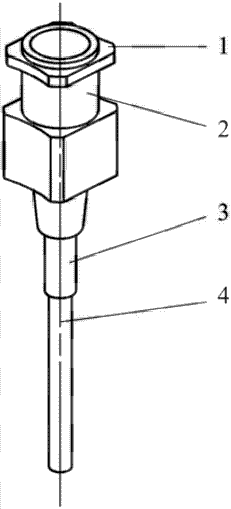
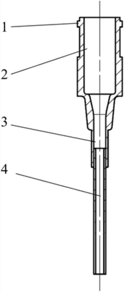
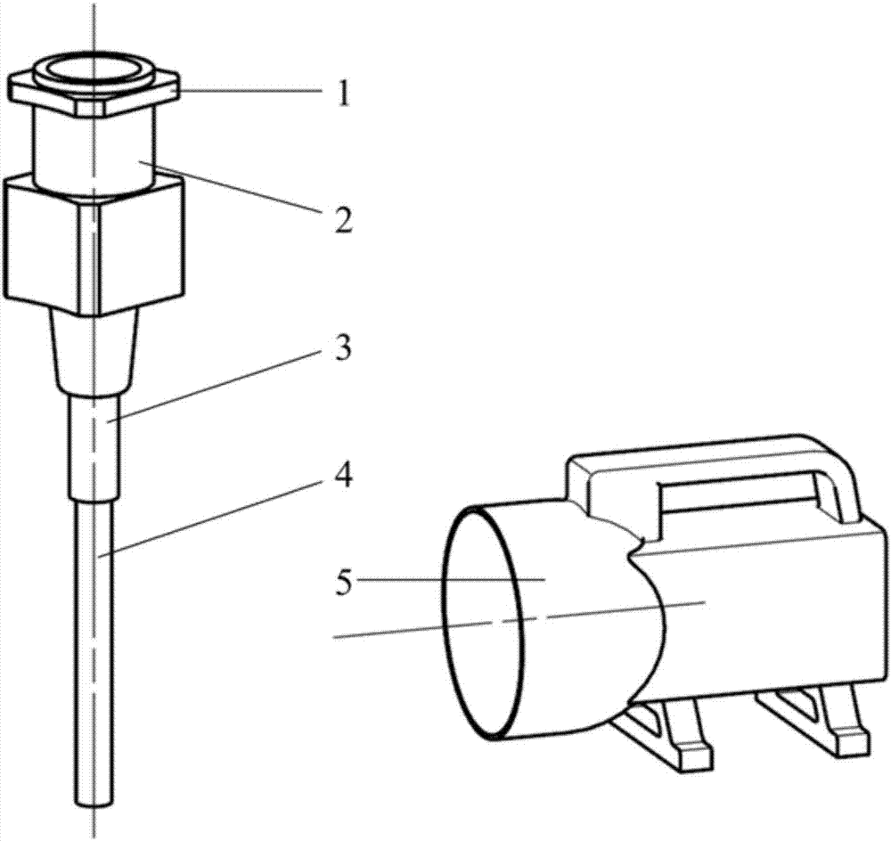
[0030] like Figure 1a and Figure 1b As shown, a 3D printing nozzle structure includes a connecting seat 1 , a feed liquid storage pipe 2 , an opaque injection head 3 , and a light-transmissive injection head 4 .

[0031] like Figure 1a and Figure 1b As shown, the top of the print nozzle is a connecting seat 1 , the bottom of the connecting seat 1 is connected to the feeding liquid storage pipe 2 , and the connecting seat 1 communicates with the inner cavity of the feeding liquid storing pipe 2 . At the same time, the connection base 1 and the feeding liquid storage pipe 2 are connecting bodies, which are provided with connection structures such as connection grooves, connection ears, connection threads, connection holes, connection clips, etc., to facilitate the assembly of the nozzle structure on the printer.

[0032]The light-tight injection head 3 and the light-transmissible injection head 4 are connected into one body, and the inner cavities of the two injection heads...


PUM


Abstract

The invention discloses a 3D printing sprayer which comprises a sprayer body with an inner cavity. A lightproof injection head and a light permeable injection head coaxial with the lightproof injection head are fixed to the bottom of the sprayer body. The light permeable injection head is fixed to the bottom of the lightproof injection head. The inner cavity of the sprayer body communicates with an inner cavity of the lightproof injection head and an inner cavity of the light permeable injection head. Different from a traditional photocuring printing system, the sprayer structure adopts the mode that the lightproof injection head and the light permeable injection head are connected and communicate with each other so that the injectors of the sprayer structure can be formed. Cross-linking curing can be achieved under uniform irradiation under ultraviolet light. In the whole process from entering the light permeable injection head to final extrusion, a photocuring material completes partial cross-linking curing, and the photocuring material adheres to a curing material on the upper layer due to viscosity of the photocuring material till printing of a complex three-dimension solid structure is completed.

Description

technical field [0001] The invention relates to a print nozzle structure, in particular to a 3D print nozzle. Background technique [0002] Stereolithography printing technology is to design a three-dimensional solid model through CAD, use discrete programs to slice the model, design the scanning path of the laser, and use the generated data to accurately control the movement of the laser scanner and the lifting platform. Then use a laser with a specific wavelength and intensity to irradiate the surface of the light-curing material according to the designed scanning path, so that it is solidified sequentially from point to line and from line to surface, so that a layer of resin in a specific area of ​​​​the surface is cured, and then the lifting table is in the vertical position. The height of one layer is lowered in the direction, and the cured layer will be covered with another layer of liquid resin, and then the second layer of scanning is performed to cure another layer....

Claims


Application Information

Patent Timeline
Patent Type & Authority Applications(China)
IPC IPC(8): B29C64/209B33Y30/00
CPCB33Y30/00
Inventor 贺永刘宇陈子辰傅建中
Owner ZHEJIANG UNIV
Why Eureka
Try Eureka