Tetrafluoroethylene (TFE) refining method

A refining method and tetrafluoroethylene technology, which are applied in chemical instruments and methods, halogenated hydrocarbon preparation, halogenated hydrocarbon disproportionation separation/purification, etc. The effect of reducing energy consumption and optimizing separation conditions

Inactive Publication Date: 2017-06-20
福建三农新材料有限责任公司
View PDF2 Cites 0 Cited by
  • Summary
  • Abstract
  • Description
  • Claims
  • Application Information

AI Technical Summary

Problems solved by technology

[0002] like figure 1 Shown, the cracking gas TFE (being tetrafluoroethylene) rectification flow process in the traditional tetrafluoroethylene production is, the first separation tower removes light components and reclaims TFE monomer, and tower bottom liquid enters rectification tower, from tower top To purify TFE monomer, the liquid in the bottom of the tower enters the second separation tower, separates Y3 (i.e. trifluoroethylene), recycles TFE, and the liquid in the bottom of the second separation tower enters the heavy component recovery system, which is difficult to improve the purity of TFE and consumes a lot of energy. All equipment, including the main line of rectification, has the risk of high toxicity hazards such as octafluoroisobutene
[0003] The specific performance is: it is difficult to improve the purity of TFE, and there are a large number of heavy components such as R22 (ie difluorochloromethane) in the rectification tower, occupying a large amount of equipment space, which limits the further improvement of the purity of TFE;
[0004] Large energy consumption, a large amount of R22 and other heavy components are repeatedly distilled in the rectification tower and the second separation tower, consuming a lot of energy;

Method used


Image

  • Tetrafluoroethylene (TFE) refining method
  • Tetrafluoroethylene (TFE) refining method

Examples


Embodiment 1

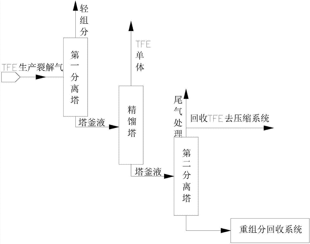
[0043] Please refer to figure 2 , a method for refining tetrafluoroethylene, comprising the steps of:

[0044] Step 1. After the cracked gas produced by TFE is sent to the first separation tower for separation, TFE is recovered from the top gas of the first separation tower, and the crude gas of the first separation tower is discharged from the middle of the first separation tower and then passed into rectification Tower, the liquid in the bottom of the first separation tower enters the heavy component recovery system;

[0045] Wherein, the pressure inside the tower of the first separation tower is controlled at 1.2MPa, and the temperature is controlled at 2.5°C;

[0046] Step 2, after the crude gas of the first separation tower enters the rectification tower for rectification, the TFE monomer is obtained from the top of the rectification tower, and the tower still liquid of the rectification tower enters the second separation tower;

[0047] Among them, the pressure inside...

Embodiment 2

[0051] Please refer to figure 2 , a method for refining tetrafluoroethylene, comprising the steps of:

[0052]Step 1. After the cracked gas produced by TFE is sent to the first separation tower for separation, TFE is recovered from the top gas of the first separation tower, and the crude gas of the first separation tower is discharged from the middle of the first separation tower and then passed into rectification Tower, the liquid in the bottom of the first separation tower enters the heavy component recovery system;

[0053] Among them, the pressure inside the first separation tower is controlled at 1.1MPa, and the temperature is controlled at -15°C;

[0054] Step 2, after the crude gas of the first separation tower enters the rectification tower for rectification, the TFE monomer is obtained from the top of the rectification tower, and the tower still liquid of the rectification tower enters the second separation tower;

[0055] Among them, the pressure inside the rectif...

Embodiment 3

[0059] Please refer to figure 2 , a method for refining tetrafluoroethylene, comprising the steps of:

[0060] Step 1. After the cracked gas produced by TFE is sent to the first separation tower for separation, TFE is recovered from the top gas of the first separation tower, and the crude gas of the first separation tower is discharged from the middle of the first separation tower and then passed into rectification Tower, the liquid in the bottom of the first separation tower enters the heavy component recovery system;

[0061] Wherein, the pressure inside the tower of the first separation tower is controlled at 1.3MPa, and the temperature is controlled at 20°C;

[0062] Step 2, after the crude gas of the first separation tower enters the rectification tower for rectification, the TFE monomer is obtained from the top of the rectification tower, and the tower still liquid of the rectification tower enters the second separation tower;

[0063] Among them, the pressure inside ...


PUM


Abstract

The invention provides a tetrafluoroethylene (TFE) refining method, which comprises the following steps of 1, conveying TFE production pyrolysis gas into a first separation tower to be separated; recovering TFE from tower top gas of the first separation tower; introducing coarse gas of the first separation tower into a rectification tower after the coarse gas of the first separation tower is exhausted from the middle part of the first separation tower; enabling tower kettle liquid of the first separation tower to enter a heavy ingredient recovery system; 2, after the coarse gas of the first separation tower enters the rectification tower to be subjected to rectification, obtaining TEF monomers from the tower top of the rectification tower; enabling tower kettle liquid of the rectification to enter a second separation tower. The TFE refining method has the beneficial effects that the first separation tower middle part side line production scheme is used; light ingredients are produced from the tower top of the first separation tower and enter a TFE recovery system for recovering TFE and then discharging light ingredients; middle part side line TFE coarse gas enters the rectification tower, and the TFE monomers with the purity being greater than 99.9999 percent can be obtained from the tower top of the rectification tower.

Description

technical field [0001] The invention relates to the technical field of tetrafluoroethylene purification, in particular to a method for refining high-purity tetrafluoroethylene. Background technique [0002] Such as figure 1 Shown, the cracking gas TFE (being tetrafluoroethylene) rectification flow process in the traditional tetrafluoroethylene production is, the first separation tower removes light components and reclaims TFE monomer, and tower bottom liquid enters rectification tower, from tower top To purify TFE monomer, the liquid in the bottom of the tower enters the second separation tower, separates Y3 (i.e. trifluoroethylene), recycles TFE, and the liquid in the bottom of the second separation tower enters the heavy component recovery system, which is difficult to improve the purity of TFE and consumes a lot of energy. All equipment, including the main line of rectification, has risks of high toxicity hazards such as octafluoroisobutene. [0003] The specific perfor...

Claims


Application Information

Patent Timeline
Patent Type & Authority Applications(China)
IPC IPC(8): C07C17/38C07C17/383C07C21/185
CPCC07C17/38C07C17/383C07C21/185
Inventor 余道腾徐万鑫徐美燚
Owner 福建三农新材料有限责任公司
Why Eureka
Try Eureka