Barrel-plating device and barrel-plating system
A barrel plating and circulation device technology, applied in the direction of cells, electrolysis process, electrolysis components, etc., can solve the problems such as floating objects cannot be discharged in time, affecting the quality of electroplating of the workpiece to be plated, and too many electroplating solutions.
- Summary
- Abstract
- Description
- Claims
- Application Information
AI Technical Summary
Problems solved by technology
Method used
Image
Examples
Embodiment 1
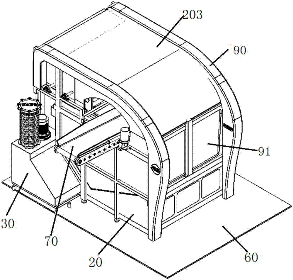
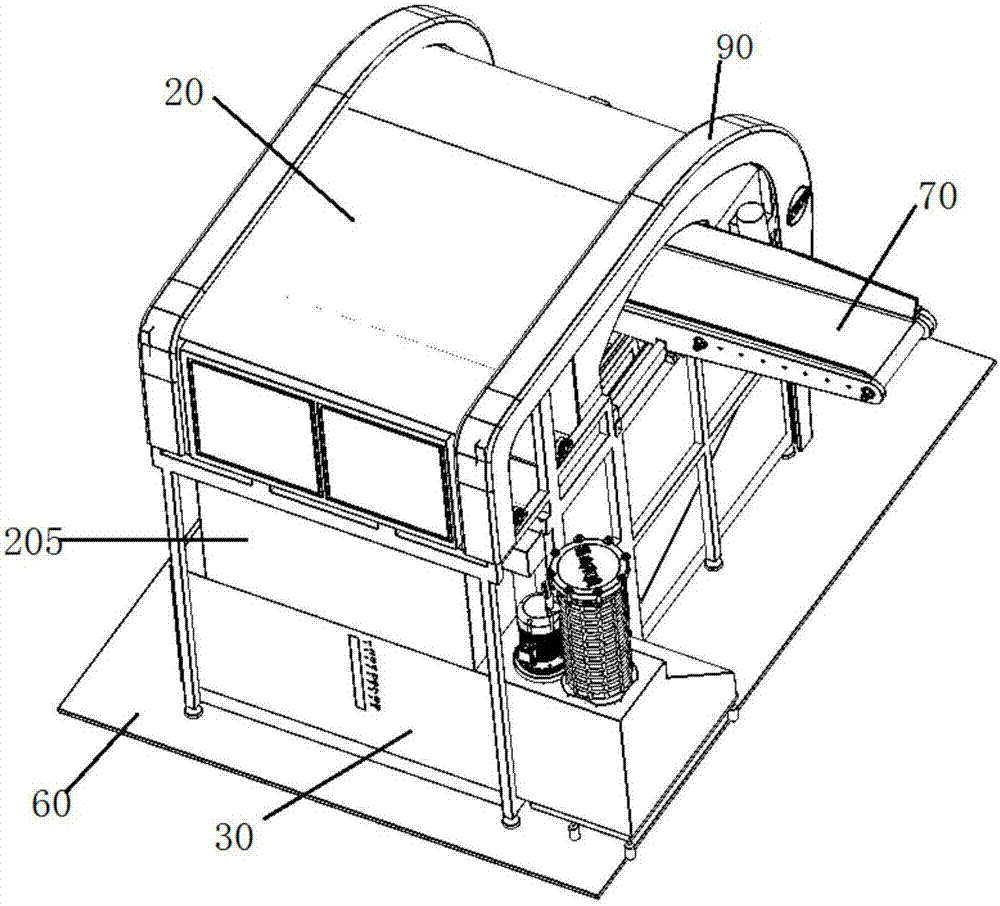
[0094] This embodiment provides a barrel plating device, such as figure 1 and figure 2 As shown, it includes a first tank 20 , a barrel coating barrel 10 , a circulation device 30 and a discharge mechanism 70 .
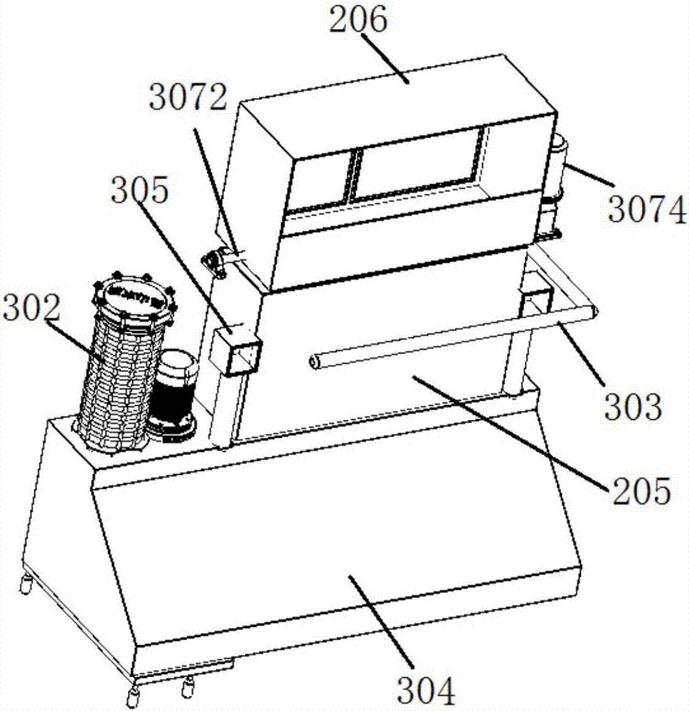
[0095] Wherein, the first tank 20 has an inner cavity, and a first inlet and a first outlet are respectively set on the opposite side walls; the barrel 10 is rotatably arranged in the inner cavity of the first tank 20 by a rotating mechanism, There are feed inlets and discharge outlets on the two side end faces, and overflow holes 1084 located below the feed inlet and the discharge outlet are provided on the two side end faces; the feed inlet corresponds to the first inlet, and the discharge port corresponds to the first inlet. The first outlet; the inner cavity of the barrel plating barrel 10 communicates with the inner cavity of the first tank 20; one end of the circulation device 30 is connected to the overflow hole 1084, and the other end is located in the barre...
Embodiment 2
[0147] This embodiment provides a barrel plating device, such as Figure 19 As shown, the difference between it and the barrel plating device provided in Example 1 is only that the structure of the barrel plating barrel 10 is different, and the barrel plating barrel 10 in this embodiment only has the first section 1011 and the second section 1012, and does not A third section 1013 is provided, that is, a dial member 103 is provided on one side of the scoop member 102, and other structures are the same as those in Embodiment 1.
Embodiment 3
[0149] This embodiment provides a barrel plating device, such as Figure 22 As shown, the difference with the barrel plating device provided in Embodiment 1 or Embodiment 2 is only that: the structure of the first section 1011 of the barrel plating barrel 10 is different, and the first section 1011 is not formed by connecting each scoop material piece 102 end to end. The first section 1011 is a cylindrical hollow cylinder, and the scooping material 102 is a plate, which is evenly distributed on the circumferential inner wall of the hollow cylinder. Of course, several scooping material 102 can also be unevenly distributed on the hollow cylinder. At this time, the connecting end 10211 of the scoop material member 102 is directly fixed on the wall surface of the first section 1011, and in the discharging state, the tilting end 10212 is formed between the circumferential wall surface of the first section 1011. The scoop area 105 with the opening facing upwards. Other structures a...
PUM
 Abstract
Description
Claims
Application Information
 - R&D
- Intellectual Property
- Life Sciences
- Materials
- Tech Scout
- Unparalleled Data Quality
- Higher Quality Content
- 60% Fewer Hallucinations
Browse by: Latest US Patents, China's latest patents, Technical Efficacy Thesaurus, Application Domain, Technology Topic, Popular Technical Reports.
© 2025 PatSnap. All rights reserved.Legal|Privacy policy|Modern Slavery Act Transparency Statement|Sitemap|About US| Contact US: help@patsnap.com


