Eureka AIR delivers breakthrough ideas for toughest innovation challenges, trusted by R&D personnel around the world.

Oscillating diode electroplating machine

An electroplating machine and diode technology, which is applied to circuits, electrolytic processes, electrolytic components, etc., can solve the problems of unqualified quality, bent leads of diodes, and unstable coefficient of variation of diodes, and achieves the effect of uniform plating thickness and less coefficient of variation.

Inactive Publication Date: 2018-01-05
张晓宇
View PDF0 Cites 6 Cited by
  • Summary
  • Abstract
  • Description
  • Claims
  • Application Information

AI Technical Summary

Problems solved by technology

However, the electroplating method in the prior art is easy to bend the lead wire of the diode, and the thickness of the electroplating layer is uneven during electroplating, and the coefficient of variation of the diode is large and unstable, which easily causes the problem of unqualified quality.

Method used


Image

  • Oscillating diode electroplating machine

Examples


Embodiment Construction

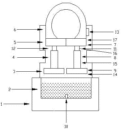
[0012] Attached below figure 1 The present invention will be further described with specific embodiments.

[0013] Such as figure 1 Shown, the present invention: the oscillating diode electroplating machine is composed of electroplating machine body 1, electroplating tank 2, variable resistance box 13, hydraulic lifting shaft 16, oscillator 17, transmission vibration shaft 16, oscillating electroplating motor 6, vibrating screen 14 and Composed of conductive nails 10, it is characterized in that: the lower end of the electroplating machine body 1 is provided with an electroplating tank 2, the bottom of the electroplating tank 2 is provided with a conductive nail 10, and the upper end of the electroplating machine body 1 is provided with an oscillating electroplating motor 6. The motor 6 is fixedly connected to the oscillator 17, the lower end of the oscillator 17 is connected to the upper end of the hydraulic lifting shaft 16, the lower end of the hydraulic lifting shaft 16 i...


PUM


Abstract

The invention discloses an oscillating diode electroplating machine which is composed of an electroplating machine body, an electroplating tank, a variable resistance box, hydraulic transmission shafts, two oscillators, oscillation-transmitting shafts, an oscillating electroplating motor, oscillating screens and a conductive nail. The electroplating tank is arranged at the lower end of the electroplating machine body; the conductive nail is arranged at the bottom of the electroplating tank; the oscillating electroplating motor is arranged at the upper end of the electroplating machine body andfixedly connected with the oscillators; the lower ends of the oscillators are connected with the upper ends of hydraulic lifting shafts, and the lower ends of the hydraulic lifting shafts are connected with the upper ends of the oscillation-transmitting shafts; and the lower ends of the oscillation-transmitting shafts are connected with the oscillating screens, and the variable resistance box ismounted on the oscillating electroplating motor. The oscillating diode electroplating machine has the beneficial effects that the oscillating electroplating motor, the two oscillators, the two hydraulic lifting shafts and the variable resistance box are arranged, the lifting shafts drive the oscillating screens to move from top to bottom, a lead is not prone to be bent, the quality of the lead isguaranteed, the electroplating thickness can be uniform, the variation coefficients are few, the rotating speed of the oscillating electroplating motor can further be increased by increasing a current, and thus the electroplating efficiency is improved.

Description

technical field [0001] The invention relates to the field of electroplating machines, in particular to an oscillating diode electroplating machine. Background technique [0002] Diode lead electroplating machine has methods such as barrel plating and rack plating. Plating is suitable for electroplating of small parts that cannot be or are not suitable for hanging due to factors such as shape and size. It adopts rack plating or basket plating for early small parts electroplating. Compared with it, it saves labor, improves labor production efficiency, and greatly improves the surface quality of the plated parts. Rack plating is that the workpiece is clamped on the rack, which is suitable for large parts. The number of products that can be plated in each batch is small, and the thickness of the coating is 10 μm. above process. However, the electroplating method in the prior art is easy to bend the lead wire of the diode, and the thickness of the electroplating layer is uneven ...

Claims


Application Information

Patent Timeline
Patent Type & Authority Applications(China)
IPC IPC(8): C25D17/16C25D5/20C25D7/12C25D21/12
Inventor 张晓宇
Owner 张晓宇
Why Eureka
Eureka Blog
Learn More