
Three-dimensional energy-efficient excavation machine

A high-efficiency energy-saving, excavation machinery technology, applied in the field of machinery

Inactive Publication Date: 2017-06-20
LIUZHOU JINGYANG ENERGY SAVING TECH RES DEV
View PDF0 Cites 0 Cited by
  • Summary
  • Abstract
  • Description
  • Claims
  • Application Information

AI Technical Summary

Problems solved by technology

[0003] The object of the present invention is to aim at the defects of the existing related technologies, and provide a technical structure with compact structure, multi-functional and practical, common for water and land excavation, deep water operation, self-moving deep rod maintenance stability, wider construction radius, small body, large buoyancy, and easy operation. Three-dimensional high-efficiency and energy-saving excavation machinery that is flexible and convenient, highly efficient, energy-saving and environmentally friendly, lower in manufacturing costs, safe, reliable and durable, and more cost-effective

Method used


Image

  • Three-dimensional energy-efficient excavation machine

Examples


example

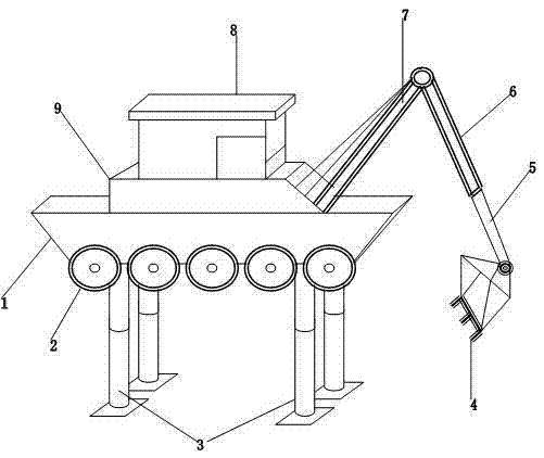
[0019] Drive the three-dimensional high-efficiency and energy-saving excavation machine to the land or water surface construction site. If land construction is carried out, the high-efficiency excavation work can be carried out by operating in the driving control room 8 according to the operation mode of an ordinary land excavation rig. If excavation and dredging constructions such as general shallow water surface and ditches are carried out, only the floating wheel 2 switch needs to be opened in the control room 8 to drive the floating hull 1 into shallow water areas and ditches, and only the floating wheel 2 or the floating hull 1 can be used. Or use the buoyancy of the floating wheel 2 and the floating hull 1 to support the body simultaneously and carry out the construction with the operation mode of the common drilling rig. If the construction in deep water area, the hydraulic switch in the control room 8 can be used to extend the water column 3 from the floating hull 1 sect...


PUM


Abstract

The invention discloses a three-dimensional energy-efficient excavation machine. The three-dimensional energy-efficient excavation machine is composed of a floating ship body, floating wheels, water bottom columns, a cab, a transfer machine, a digging bucket, a digging arm, an auxiliary driving arm and a main driving arm of a main body and a digging device. The floating ship body is arranged at the lower side of the transfer machine. The floating wheels are arranged at the two sides of the floating ship body. The water bottom columns are symmetrically hidden on the inner side of the floating ship body. The cab is arranged at the upper side of the transfer machine. The transfer machine is arranged at the upper side of the floating ship body, and the upper side of the transfer machine is connected with the lower side of the cab. The digging bucket is arranged at the lower end of the digging arm. The lower end of the digging arm is movably connected with the digging bucket, and the upper end of the digging arm is connected to the inner side of the auxiliary driving arm in a sleeved mode. The lower end of the auxiliary driving arm is connected to the upper end of the digging arm in a sleeving mode, and a through hole in the upper end of the auxiliary driving arm is connected to the outer side of a gear shaft at the upper end of the main driving arm in a sleeving mode. The lower end of the main driving arm is arranged on the inner side of the transfer machine, and the upper end of the main driving arm is connected with the auxiliary driving arm in a matched mode. The three-dimensional energy-efficient excavation machine is exquisite in technological structure, multifunctional, wide in practicability, capable of being commonly used for water and land digging and carrying out deepwater operation, stable in maintenance of self-moving deep rods, wider in construction radius, small in size, high in buoyancy, flexible, convenient and fast to operate, high in efficiency, capable of achieving energy saving and environmental protection, safe, reliable, durable in use and high in comprehensive cost performance.

Description

technical field [0001] The invention relates to a machine, in particular to a three-dimensional high-efficiency and energy-saving excavation machine. Background technique [0002] In the process of industrial and agricultural production and construction, it is often necessary to carry out land and underwater excavation, leveling, dredging, drilling, smashing and planing, etc., while the existing general mechanical equipment and tools have many names, but most of them are used on land. Water surface construction cannot be carried out, while the design technology of general ship-type drilling rigs is lagging behind, unreasonable structure, single function, heavy buoyancy, low buoyancy, no stable device, difficult construction operation, difficult to operate in deep water, poor construction effect, low safety and energy saving rate. For this reason, it is extremely necessary to invent a kind of three-dimensional high-efficiency energy-saving excavating machine that can overcome...

Claims


Application Information

Patent Timeline
IPC IPC(8): E02F5/28
Inventor 韦战
Owner LIUZHOU JINGYANG ENERGY SAVING TECH RES DEV
Learn More