Centrifugal type slurry pump

A centrifugal and slurry technology, applied in the direction of non-variable pumps, non-volume pumps, pumps, etc., can solve the problems of large cooling water consumption, increased wastewater treatment pressure, increased environmental protection costs, etc., to improve sealing safety , Reduce frictional resistance, effective cooling function

Pending Publication Date: 2017-06-20
宜兴市宙斯泵业有限公司
View PDF9 Cites 0 Cited by
  • Summary
  • Abstract
  • Description
  • Claims
  • Application Information

AI Technical Summary

Problems solved by technology

Flushing with cooling water can properly increase the service life of the seal, but it must consume a large amount of cooling water. Each pump consumes more than 4 tons of water resources per day. At the same time, secondary pollution of cooling water will occur, increasing the pressure of wastewater treatment. thereby increasing environmental costs
[0004] Furthermore, in the original technology, the seal of the slurry pump cannot run dry without liquid, and the seal will be damaged immediately if it is operated without external cooling water
[0005] Therefore, the above-mentioned shortcomings are problems that have been difficult to solve in the industry for a long time, and there is no effective solution so far, and there is no product that can effectively overcome such problems on the market, so there is still room for innovation and improvement

Method used


Image

  • Centrifugal type slurry pump
  • Centrifugal type slurry pump
  • Centrifugal type slurry pump

Examples


Embodiment 1

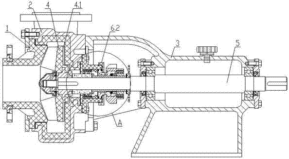
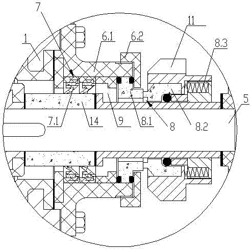
[0042] Embodiment 1: see Figure 1~9 , a centrifugal slurry pump, the slurry pump is a front suction type, including a pump cover 1 with an open front end, a pump casing 2 connected to the pump cover 1, a bearing seat 3 connected to the pump casing 2, and a The impeller 4 in 2 is connected with the impeller 4 to the rotating main shaft 5, and the rotating main shaft 5 protrudes out of the pump casing 2 to connect with the bearing seat 3. A shaft seal is provided at the contact between the rotating main shaft 5 and the pump casing 2, and the shaft sealing includes connection with the pump casing 2. The sealing box 6.1, the sealing box gland 6.2, the main seal 7 on the side of the pump casing 2, the auxiliary seal 8 on the rear side of the main seal 7, the auxiliary seal 8 is an external mechanical seal, and the external mechanical seal includes a static ring 8.1, a dynamic Ring 8.2 and metal spring 8.3, static ring 8.1 are compressed by the sealing box gland 6.2, the main seal ...

Embodiment 2

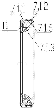
[0044] Example 2: see Figure 10 , 11 , a centrifugal slurry pump, the slurry pump is a side suction type, including a pump cover 1 sealed at the front end, a pump casing 2 connected to the pump cover 1, a bearing seat 3 connected to the pump casing 2, and a The impeller 4 in 2 is connected with the impeller 4 to the rotating main shaft 5, and the rotating main shaft 5 extends out of the pump casing 2 to connect with the bearing seat 3. A shaft seal is provided at the contact between the rotating main shaft 5 and the pump casing 2, and the shaft sealing includes a sealing box 6.1, Seal box gland 6.2, main seal 7 on the side of the pump casing 2, secondary seal 8 on the rear side of the main seal 7, the secondary seal 8 is a mechanical seal, the pump casing 2 is connected to the suction tee 13, and the shaft sleeve 14 is set on the rotating On the main shaft 5, the main seal 7 is composed of two lip seal rings 7.1 superimposed, the lip seal ring 7.1 is a seal ring with a filte...

Embodiment 3

[0058] Embodiment 3: (see Figure 12 , 13 ) The net liquid in the net liquid chamber 9 in the combined seal of the centrifugal slurry pump described in Embodiments 1 and 2 can be obtained and replenished from the external filling liquid port 6.1.1 on the sealing box 6.1 (such as Figure 12 ). The centrifugal slurry pump with this sealing structure can be applied to the post of conveying thick slurry, and a small amount of net liquid can be injected into the pump cavity from the lip and through passage of the rubber lip seal ring to flush the sealing part, as long as a small amount of water is consumed It can also have better sealing cooling and flushing effect.

[0059] In order to flush out the slurry particles entering the liquid chamber due to the failure of the lip seal ring, a better method is to set the slag discharge port 6.1.2 on the lower side of the seal box (such as Figure 13 ), for easy flushing and maintenance.

[0060]In the above embodiment, the liquid inje...


PUM


Abstract

The invention discloses a centrifugal type slurry pump. The centrifugal type slurry pump comprises a pump cover, a pump shell connected with the pump cover, a bearing base connected with the pump shell, an impeller positioned in the pump shell and a rotary main shaft connected with the impeller, wherein the rotary main shaft extends out of the pump shell, and is connected with the bearing base; a shaft seal is arranged on a contact part of the rotary main shaft and the pump shell; the shaft seal comprises a sealing box connected with the pump shell, a sealing box pressure cover, a main seal close to the pump shell side, and a secondary seal at the rear side of the main seal; the secondary seal is an external type mechanical seal; the main seal is formed by superposing a plurality of lip-shaped sealing rings; the lip-shaped sealing rings are sealing rings with filter devices; each sealing ring with the filter device comprises a ring-shaped rubber basal body and a reinforcing framework embedded into the rubber basal body, wherein a sealing lip is arranged at the inner ring of the rubber basal body, one side of the rubber basal body is a flow-in side, the other side of the rubber basal body is a flow-out side, a filter part is arranged between the rubber basal body and the sealing lip, and the filter part comprises an accommodating cavity filled with a filter element body and a penetrating channel for enabling the accommodating cavity to communicate with the flow-out side of the rubber basal body;and slurry enters each accommodating cavity from the corresponding flow-in side, and is filtered through the corresponding filter element body, so that filtered clean liquor enters the corresponding flow-out side from the corresponding penetrating channel.

Description

technical field [0001] The invention relates to the field of centrifugal pump manufacture. Background technique [0002] Centrifugal slurry pump is a common conveying equipment used to transport various slurries in the industrial field. It is widely used in chemical industry, smelting, mineral product processing, environmental protection engineering and other industrial fields. At present, there are several centrifugal slurry pumps in operation in China. million units. [0003] Commonly used seals for centrifugal slurry pumps include double-end mechanical seals, lip-shaped rubber dynamic seals, packing seals, etc. These seals have two problems that have been difficult to solve for a long time, namely: first, solids such as sand will enter the seal combination, The shaft seal is worn out; the second is that no matter what kind of pump shaft seal it is, it will damage the seal due to rotation, friction and heat. In order to solve the above problems, the common method is to c...

Claims


Application Information

Patent Timeline
IPC IPC(8): F04D7/04F04D29/12F04D29/58F04D29/70F04D29/22
CPCF04D7/04F04D29/126F04D29/2222F04D29/588F04D29/708
Inventor 蒋龙福蒋凌超
Owner 宜兴市宙斯泵业有限公司
Why Eureka
Try Eureka