Sand prevention device of submersible pump motor

A technology for submersible pumps and motor shafts, which is applied to components, pumps, and pump components of pumping devices used for elastic fluids. It can solve problems such as burning motors, affecting work progress, and increasing costs, so as to ensure airtight performance, The effect of improving the service life and good sealing effect

Inactive Publication Date: 2017-06-20
TIANJIN ZHENDA PUMP CO LTD
View PDF0 Cites 3 Cited by
  • Summary
  • Abstract
  • Description
  • Claims
  • Application Information

AI Technical Summary

Problems solved by technology

Existing submersible motors have strict requirements on the water quality of the conveyed water. The national standard stipulates that the content of mud and sand in the water is not more than 0.01%, but in actual work, it is often much greater than this value, because mud and sand can easily enter between the motor shaft and the dynamic seal. , so that the motor shaft and seal are damaged early due to the rapid wear of mud and sand, which greatly reduces the service life of the submersible motor, affects the work progress, and increases the cost
At present, some submersible motors only set a sand sealing cover on the upper end of the sealing groove of the submersible motor. This setting cannot effectively block the mud and sand, so that the mud and sand will accumulate in the sealing groove of the submersible motor through the sand sealing cover. Through the continuous rotation of the submersible motor, the The mud and sand are brought into the interior of the submersible motor, reducing the service life of the submersible motor
The sand-proof structure of some submersible motors uses a cast iron sand throwing ring to connect the motor shaft through a flat key, and the upper part of the sand throwing ring is a plane, but there is a gap at the connection in this way, which is easy to accumulate mud and sand, which will cause mud and sand to pass through the gap along the motor shaft. The shaft enters the inner cavity of the guide bearing seat, eventually causing rapid wear of the oil seal and guide bearing, and even burning the motor

Method used


Image

  • Sand prevention device of submersible pump motor
  • Sand prevention device of submersible pump motor

Examples


Embodiment Construction

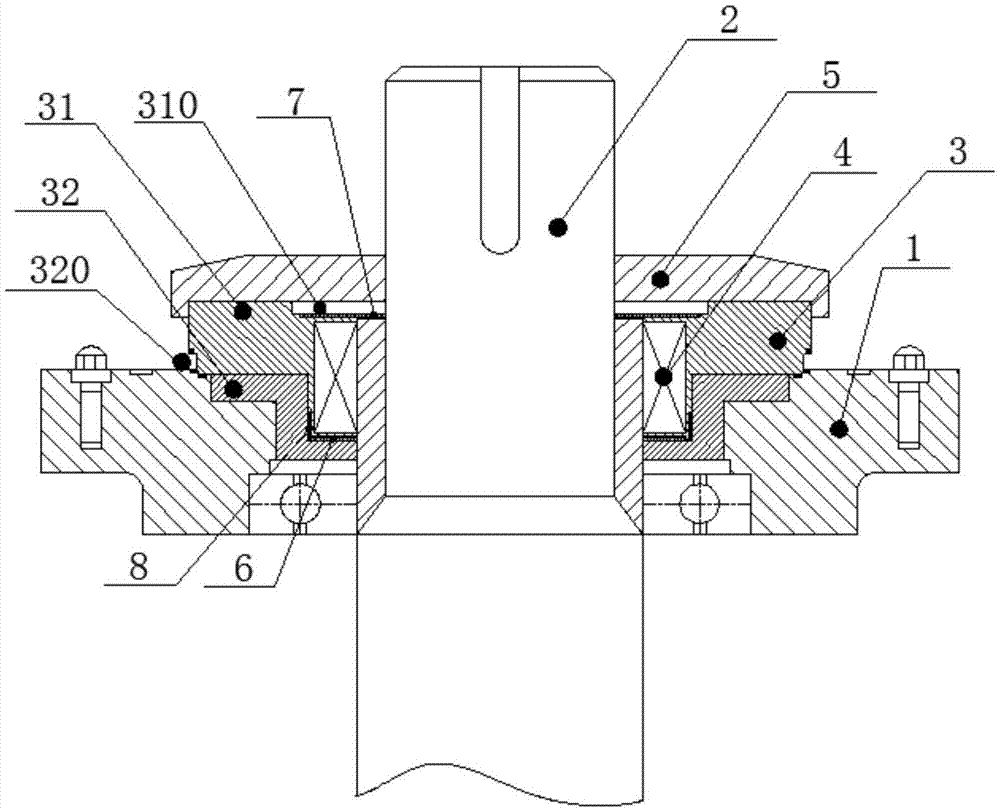
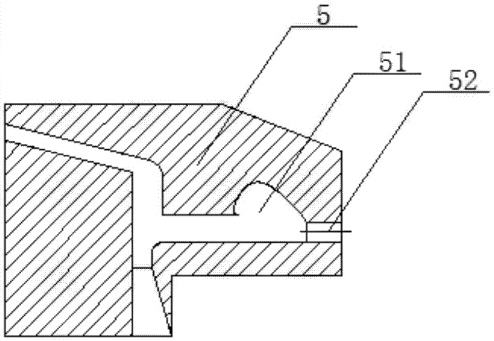
[0017] Such as figure 1 As shown, the present invention provides a sand control device for a submersible pump motor, including a motor casing 1, a motor shaft 2, a sealing end cover 3, a skeleton oil seal 4 and a sand throwing ring 5, wherein the sand throwing ring 5 is sleeved on the motor shaft 2 on, and located above the sealing end cap 3.

[0018] The sealing end cap 3 includes an upper sealing end cap 31 and a lower sealing end cap 32. A plane and a positioning circular step 310 are processed on the inner side of the upper sealing end cap 31. The upper part of the skeleton oil seal 4 is fixedly installed on the positioning circular step 310. The motor The shaft is also sleeved with a sealing ring 7 located on the upper part of the skeleton oil seal, and the skeleton oil seal 4 and the sealing ring 7 are attached together. The bottom of the frame oil seal 4 is provided with an anti-friction sheet 6, the anti-friction sheet 6 is located between the frame oil seal 4 and the...


PUM


Abstract

The invention provides a sand control device for a submersible pump motor, which includes a motor casing, a motor shaft, a sealing end cover, a skeleton oil seal and a sand throwing ring, wherein the sand throwing ring is sleeved on the motor shaft and is located above the sealing end cover; the sealing end The cover includes an upper sealing end cover and a lower sealing end cover. A plane and a positioning circular step are processed on the inner side of the upper sealing end cover. The skeleton oil seal is fixedly installed on the positioning circular step. Between the skeleton oil seal and the lower sealing end cover, the top end of the edge of the lower sealing end cover is sealed and welded to the shell wall of the motor casing. The invention has the beneficial effects of good sealing performance and high production efficiency, can effectively prevent mud and sand from entering the motor, and improve the service life of the submersible motor.

Description

technical field [0001] The invention relates to a sealing structure, in particular to a sand control device for a submersible pump motor. Background technique [0002] The submersible motor works in water, and anti-silt and water tightness are one of the important characteristics of the submersible motor. Existing submersible motors have strict requirements on the water quality of the conveyed water. The national standard stipulates that the content of mud and sand in the water is not more than 0.01%, but in actual work, it is often much greater than this value, because mud and sand can easily enter between the motor shaft and the dynamic seal. , so that the motor shaft and seal are damaged early due to the rapid wear of mud and sand, thereby greatly reducing the service life of the submersible motor, affecting the work progress, and increasing the cost. At present, some submersible motors only set a sand sealing cover on the upper end of the sealing groove of the submersib...

Claims


Application Information

Patent Timeline
Patent Type & Authority Applications(China)
IPC IPC(8): F04D29/10F04D29/12
CPCF04D29/106F04D29/126
Inventor 薛俊宏
Owner TIANJIN ZHENDA PUMP CO LTD
Why Eureka
Try Eureka