A temperature-controlled electromagnetic clutch

An electromagnetic clutch and electromagnet technology, applied in clutches, magnetic drive clutches, non-mechanical drive clutches, etc., can solve problems such as energy waste, inability to meet cooling requirements, and limited cooling range, ensuring equipment service life and working temperature. Stable, large temperature control effect

Active Publication Date: 2018-10-30
GUANGDE COUNTY HUIDA ELECTRICAL APPLIANCES
View PDF7 Cites 2 Cited by
  • Summary
  • Abstract
  • Description
  • Claims
  • Application Information

AI Technical Summary

Problems solved by technology

Solid, this kind of cooling device has the problem of energy waste, in order to solve this problem, some existing cooling devices use electromagnetic clutches and temperature control switches to control the cooling time, such as the Chinese patent No. ZL201420021271.0 discloses a The electromagnetic clutch fan cooling device for engineering machinery engines, which is connected to the inner and outer coils of the electromagnet through two temperature control switches to achieve timely cooling and cooling intensity
However, this device only achieves cooling by changing the rotating speed of the fan, and its cooling range is limited, which cannot meet the cooling needs of working for a long time in a hot climate

Method used


Image

  • A temperature-controlled electromagnetic clutch
  • A temperature-controlled electromagnetic clutch
  • A temperature-controlled electromagnetic clutch

Examples


Embodiment 1

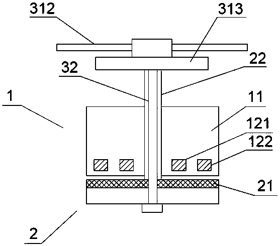
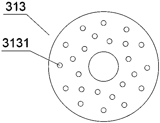
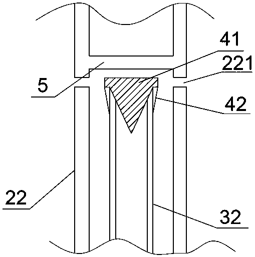
[0022] Example 1, such as Figure 1-3 As shown, the present invention includes a driving part 1, a driven part 2, a temperature control mechanism connected to the driving part 1, and a cooling mechanism connected to the driven part 2. The driving part 1 includes a pulley 11, a device The electromagnet in the pulley 11, the driven part 2 includes an armature 21, a drive shaft 22 located in the middle of the armature 21, and the electromagnet includes an inner coil 121 and an outer coil 122; the temperature control The mechanism includes a first temperature control switch connected to the outer coil 122, a second temperature control switch connected to the inner coil 121; the cooling mechanism includes an air cooling device connected to the drive shaft 22, set on the drive shaft 22 and communicate with the cooling tube 32 of the air-cooling device; the air-cooling device includes a support frame, a fan 312, a cooling plate 313 located at one end of the support frame near the fan...


PUM


Abstract

The invention provides a temperature-control electromagnetic clutch and belongs to the technical field of electromagnetic clutches. The temperature-control electromagnetic clutch comprises a driving part, a driven part, a temperature-control mechanism connected with the driving part, and a cooling mechanism connected with the driven part, wherein the driving part comprises a belt pulley and an electromagnet arranged in the belt pulley; the driven part comprises an armature and a driving shaft arranged at the middle of the armature; the electromagnet comprises an inner coil and an outer coil; the temperature-control mechanism comprises a first temperature-control switch and a second temperature-control switch; the first temperature-control switch is connected with the outer coil; the second temperature-control switch is connected with the inner coil; the cooling mechanism comprises an air cooling device and a cooling pipe; the air cooling device is connected with the driving shaft; the cooling pipe is arranged in the driving shaft and communicates with the air cooling device; the air cooling device comprises a supporting frame, a fan and a cooling disc; the cooling disc is arranged at the end, close to the fan, of the supporting frame; a cooling cavity is formed in the cooling disc; and a plurality of cooling holes which are penetrating from top to bottom are formed in the cooling disc. The temperature-control electromagnetic clutch provided by the invention has the advantages that the temperature-control range is wide, the working temperature stability can be effectively guaranteed, and the service life can be ensured.

Description

technical field [0001] The invention relates to the technical field of electromagnetic clutches, in particular to a temperature-controlled electromagnetic clutch. Background technique [0002] Because some existing equipment will generate heat during work, a cooling device is often provided to control the temperature, so as to ensure the normal operation and service life of the equipment. However, many existing cooling devices are generally started and shut down at the same time as the equipment they serve, and this type of equipment does not need to be in a cooling state all the time, it only needs to avoid its temperature being too high. Solid, this kind of cooling device has the problem of energy waste, in order to solve this problem, some existing cooling devices use electromagnetic clutches and temperature control switches to control the cooling time, such as the Chinese patent No. ZL201420021271.0 discloses a The electromagnetic clutch fan cooling device for engineeri...

Claims


Application Information

Patent Timeline
Patent Type & Authority Patents(China)
IPC IPC(8): F16D27/06F16D27/14
CPCF16D27/06F16D27/14F16D2027/008
Inventor 杜辉
Owner GUANGDE COUNTY HUIDA ELECTRICAL APPLIANCES
Why Eureka
Try Eureka