Silicone oil fan clutch

A clutch and silicone oil technology, applied in the direction of machine/engine, engine components, engine cooling, etc., can solve the problems of limited working temperature range, low control accuracy, slow response speed, etc., to achieve a simple and practical overall structure, high control accuracy, Responsive effect

Active Publication Date: 2012-06-13
WARNER SHENGLONG NINGBO CO LTD
View PDF3 Cites 0 Cited by
  • Summary
  • Abstract
  • Description
  • Claims
  • Application Information

AI Technical Summary

Problems solved by technology

[0006] The above-mentioned clutches all use temperature sensing parts to control the opening and closing of the valve plate, so there are the following disadvantages: first, the response speed is slow, and the thermal deformation speed of the bimetallic temperature sensing parts is slow; second, the control accuracy is low, and there are individual differences in the quality of the temperature sensing parts , the thermal deformation is not ideally linear; third, it is susceptible to environmental interference, and the temperature of the air blown from the radiator is affected by the ambient temperature and the distance from the radiator to the temperature sensing element; fourth, the layout is limited, in order to feel the temperature of the radiator , the distance from the temperature sensor to the radiator is limited; fifth, the operating temperature range is limited, and the thermal deformation of the temperature sensor is limited; sixth, the control element is single, and the control can only be adjusted by the temperature of the radiator; seventh, passive control , can only act after the temperature of the radiator changes; eighth, only open-loop control can be realized; ninth, only fixed and simple control logic can be realized, relying on product structure, and the structure is fixed and cannot be too complicated

Method used


Image

  • Silicone oil fan clutch
  • Silicone oil fan clutch
  • Silicone oil fan clutch

Examples


Embodiment

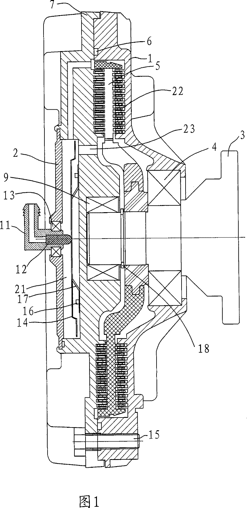
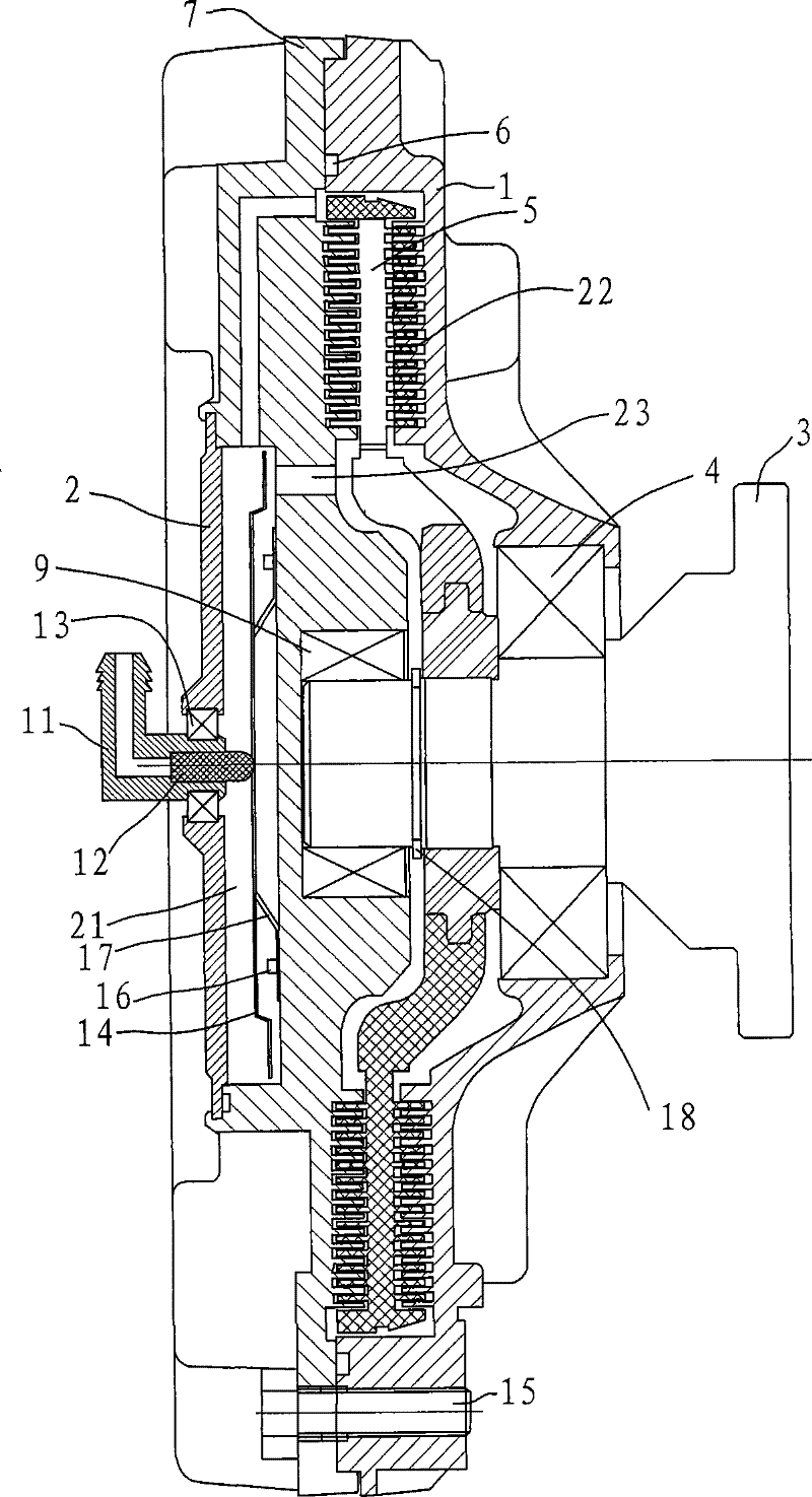
[0018] Example: such as figure 1 As shown, the silicon oil fan clutch in the present embodiment includes a housing 1, an oil storage cover 2, a valve plate 14, a front cover 7, a driving shaft 3 and a driving plate 5 arranged on the driving shaft 3, and the driving plate 3 passes through a card. The ring 18 is fixed on the drive shaft 3 and can rotate together with the drive shaft 3 . The front cover 7 is arranged on the driving shaft 3 through the front cover bearing 9, the housing 1 is arranged on the driving shaft 3 through the housing bearing 4, the front cover 7 is sealed with the housing 1, and a sealing ring 6 is arranged between them. And fixed by screw 15.

[0019] The oil storage cover 2 is arranged at the front end of the front cover 7 and forms an oil storage chamber 21 with the front cover 7, and an engagement cavity 22 is formed between the front cover 7, the housing 1 and the active plate 5, and the front cover 7 is provided with a storage chamber. The oil cha...


PUM


Abstract

The invention relates to a silicon oil fan clutch, comprising a shell, an oil storage cover, a front cover, a main drive shaft and a main drive plate arranged on the main drive shaft, wherein, the front cover is connected with the shell in a sealing way, the oil storage cover is arranged at the front end of the front cover and forms an oil storage cavity with the front cover, and the main drive plate, the front cover and the shell form a gearing cavity; besides, the front cover is provided with an oil outlet channel; an oil inlet end arranged at the oil outlet channel is provided with a valveplate which is arranged at the end surface of the front cover by an elastic work piece, and the valve plate can open the oil outlet channel as force is imposed upon the valve plate by the elastic work piece; the middle part of the front cover is provided with a through hole, a guide tube end is arranged in the through hole by a guide tube bearing, a thimble is arranged in the guide tube end and pushes against the valve plate, and a guide tube joint is externally connected with a fluid source controlled by an engine control unit. Compared with the prior art, the silicon oil fan clutch of the invention has the advantages of high precision, quick response and wide range of temperature control.

Description

technical field [0001] The invention relates to an engine cooling system assembly, in particular to a silicone oil fan clutch. Background technique [0002] Saving energy is a long-term policy of the country's economic development. According to relevant research data, 5-10% of the energy of the car is consumed by the fan cooling of the engine. In fact, the car does not need fan cooling for most of the working time, and generally only 5-10% of the time requires fan cooling. The fan automatic clutch technology is an important key technology for automobile energy saving. For this reason, many technicians have carried out technical improvements to the fan automatic clutch. They generally adopt the structure of bimetallic temperature sensing parts, through which the bimetallic temperature sensing parts feel the temperature of the air blown from the radiator to produce thermal deformation to control the switch of the valve. [0003] The existing silicon oil fan clutch for automo...

Claims


Application Information

Patent Timeline
Patent Type & Authority Patents(China)
IPC IPC(8): F01P5/04
Inventor 戴宏鸣崔华南李伟
Owner WARNER SHENGLONG NINGBO CO LTD
Why Eureka
Try Eureka