Four-quadrant-detector-based linear optical current sensor and detection method thereof

A four-quadrant detector and current sensor technology, applied in the direction of only measuring current, measuring current/voltage, measuring electrical variables, etc., can solve problems such as difficulty in meeting S-level requirements, large measurement errors, and large algorithm errors, and achieve real-time The effect of measurement, measurement resolution improvement, and cost reduction

Active Publication Date: 2017-06-20
FUZHOU UNIV
View PDF3 Cites 12 Cited by
  • Summary
  • Abstract
  • Description
  • Claims
  • Application Information

AI Technical Summary

Problems solved by technology

However, the spot image positioning method based on linear array CCD has many shortcomings, such as high cost, large algorithm error, need to convert the rotation image into a translation image, and the measurement resolution is limited by the number of optical fibers of the image converter and the pixel size of the CCD camera. etc., especially when measuring small currents, the measurement error is large due to insufficient resolution, and it is difficult to meet the S-level requirements

Method used


Image

  • Four-quadrant-detector-based linear optical current sensor and detection method thereof
  • Four-quadrant-detector-based linear optical current sensor and detection method thereof
  • Four-quadrant-detector-based linear optical current sensor and detection method thereof

Examples


Embodiment Construction

[0027] The technical solution of the present invention will be specifically described below in conjunction with the accompanying drawings.

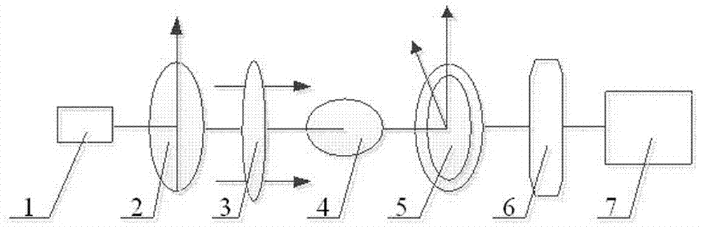
[0028] The present invention provides a linear optical current sensor based on a four-quadrant detector, such as figure 1 As shown, it includes a laser source 1, a polarizer 2, a magneto-optical film 3, a beam expander 4, a radial analyzer grating 5, a four-quadrant detector 6, and a signal processing system 7 that are sequentially arranged on the same optical path; A magnetic collecting ring with an air gap, the current-carrying wire to be detected passes through the magnetic collecting ring, and the magneto-optical film is arranged between the air gaps of the magnetic collecting ring.

[0029] Further, in this embodiment, the air gap of the magnetic collecting ring is less than 15mm, and the magnetic field is evenly distributed.

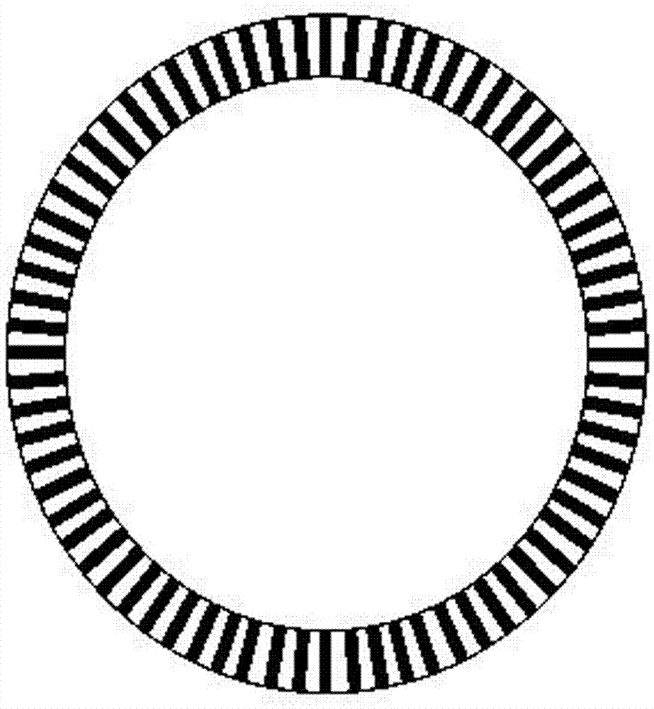
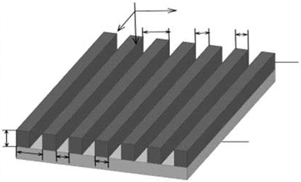
[0030] Further, in this embodiment, as figure 2 as well as image 3 As shown, the radial analyzer grati...


PUM


Abstract

The invention relates to a four-quadrant-detector-based linear optical current sensor and a detection method thereof. The linear optical current sensor comprises a laser source, a polarizer, a magneto-optical film, a beam expander, a radial polarization detection grating, a four-quadrant detector and a signal processing system that are arranged successively at one same optical path. In addition, the linear optical current sensor also includes a magnetic collection ring with air gaps; a to-be-detected current-carrying lead passes through the magnetic collection ring; and a magneto-optic thin film is arranged between the air gaps. In addition, the detection method includes: an optical signal passes through the polarizer, the magneto-optical film, the beam expander, and the radial polarization detection grating successively from the laser source and then a light spot is obtained; after the light spot passes through the four-quadrant detector, the optical signal is transformed into an electrical signal; the signal processing system collects the electrical signal and operation is carried out to obtain the size of a rotation angle, so that a to-be-detected current value in the to-be-detected current-carrying lead is obtained. Compared with the prior using the CCD camera, the sensor and the detection method enable the resolution ratio to be improved substantially, the accuracy to be enhanced, and the cost to be reduced.

Description

technical field [0001] The invention relates to a linear optical current sensor and a detection method realized based on a four-quadrant detector. Background technique [0002] Compared with the traditional electromagnetic current transformer, the optical current transformer has the advantages of simple insulation structure, no magnetic saturation, strong anti-electromagnetic interference ability, and wide measurement frequency bandwidth. It is a research hotspot for smart grid primary equipment. At present, most optical transformers use a linear array CCD (Charge Coupled Device) camera to locate the light spot to achieve current measurement, which overcomes many defects of the traditional light intensity detection mode, such as narrow dynamic measurement range, nonlinearity, optical power dependence, line Birefringence interference and temperature drift, etc., improve the practicability of the transformer. However, the spot image positioning method based on linear array CC...

Claims


Application Information

Patent Timeline
Patent Type & Authority Applications(China)
IPC IPC(8): G01R15/24G01R19/00
CPCG01R15/246G01R19/0092
Inventor 徐启峰黄奕钒项宇锴许志坤
Owner FUZHOU UNIV
Why Eureka
Try Eureka