Identification method of partial discharge fault of electrical equipment, apparatus and system thereof

A technology for power equipment and partial discharge, which is applied in the direction of testing dielectric strength, etc., can solve problems such as partial discharge fault identification that cannot satisfy a large amount of data, achieve the effect of improving recognition ability and recognition speed, and enhancing the intelligence of the power grid

Active Publication Date: 2017-06-20
BEIJING HUADIAN ZHICHENG ELECTRICAL EQUIP CO LTD
View PDF5 Cites 7 Cited by
  • Summary
  • Abstract
  • Description
  • Claims
  • Application Information

AI Technical Summary

Problems solved by technology

[0006] Embodiments of the present invention provide a method, device and system for identifying partial discharge faults of electric power equipment, at least solving the recognition scheme of partial discharge faults of electric power equipment in the prior art as stand-alone identification, which cannot meet the requirements of partial discharge faults with a large amount of data Identify technical issues

Method used


Image

  • Identification method of partial discharge fault of electrical equipment, apparatus and system thereof
  • Identification method of partial discharge fault of electrical equipment, apparatus and system thereof
  • Identification method of partial discharge fault of electrical equipment, apparatus and system thereof

Examples


Embodiment 1

[0031] According to an embodiment of the present invention, an embodiment of a method for identifying partial discharge faults of electric power equipment is provided. It should be noted that the steps shown in the flow charts of the drawings can be implemented in a computer system such as a set of computer-executable instructions and, although a logical order is shown in the flowcharts, in some cases the steps shown or described may be performed in an order different from that shown or described herein.

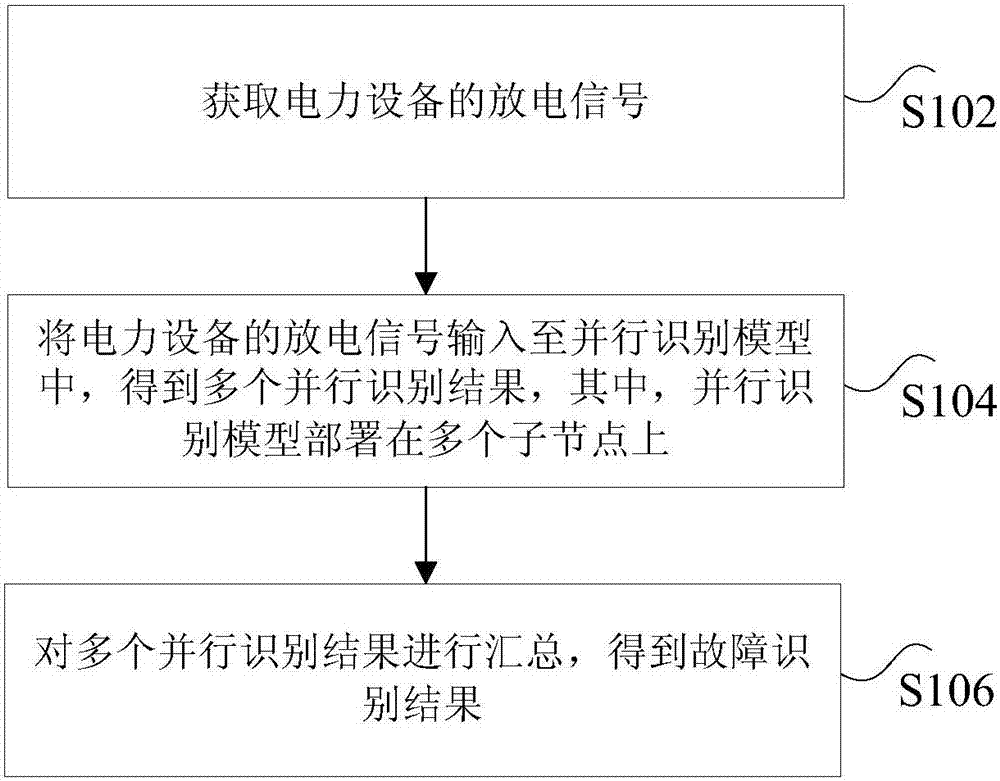
[0032] figure 1 It is a flow chart of a method for identifying partial discharge faults of power equipment according to an embodiment of the present invention, as shown in figure 1 As shown, the method includes the following steps:

[0033] Step S102, acquiring a discharge signal of the electric equipment.

[0034] Specifically, the above discharge signal may be a discharge signal actually detected by the electrical equipment due to a partial discharge fault.

[0035]Step...

Embodiment 2

[0087] According to an embodiment of the present invention, an embodiment of an identification device for a partial discharge fault of electric equipment is provided.

[0088] Figure 5 is a schematic diagram of an identification device for partial discharge faults of power equipment according to an embodiment of the present invention, as shown in Figure 5 As shown, the device includes:

[0089] The first acquiring unit 51 is configured to acquire a discharge signal of the electric equipment.

[0090] Specifically, the above-mentioned discharge signal may be a discharge signal actually detected by the electrical equipment due to a partial discharge fault.

[0091] The processing unit 53 is configured to input the discharge signal of the electric equipment into the parallel recognition model to obtain multiple parallel recognition results, wherein the parallel recognition model is deployed on multiple sub-nodes.

[0092] Specifically, in a server cluster, one server may be ...

Embodiment 3

[0130] According to an embodiment of the present invention, an embodiment of a system for identifying a partial discharge fault of electric equipment is provided.

[0131] Figure 6 is a schematic diagram of an identification system for partial discharge faults of power equipment according to an embodiment of the present invention, as shown in Figure 6 As shown, the system includes:

[0132] The master node 61 is used to acquire the discharge signal of the electric equipment.

[0133] Specifically, the above-mentioned discharge signal may be a discharge signal actually detected by the electrical equipment due to a partial discharge fault.

[0134] A plurality of sub-nodes 63 are connected to the master node, and parallel identification models are deployed on the plurality of sub-nodes for inputting discharge signals of electric equipment into the parallel identification models to obtain multiple parallel identification results.

[0135] Specifically, in a server cluster, o...


PUM


Abstract

The invention discloses an identification method of a partial discharge fault of electrical equipment, an apparatus and a system thereof. The method comprises the following steps of acquiring a discharge signal of the electrical equipment; inputting the discharge signal of the electrical equipment into a parallel identification model and acquiring a plurality of parallel identification results, wherein the parallel identification model is deployed on a plurality of sub-nodes; and gathering the plurality of parallel identification results and acquiring a fault identification result. In the prior art, an identification scheme of the partial discharge fault of the electrical equipment is single machine identification so that partial discharge fault identification of a lot of data can not be satisfied. By using the method, the apparatus and the system of the invention, the above technical problem is solved.

Description

technical field [0001] The invention relates to the field of partial discharge fault identification of high-voltage electric equipment, in particular, to a method, device and system for identifying partial discharge faults of electric power equipment. Background technique [0002] Partial discharge is a non-penetrating discharge phenomenon caused by local defects in the insulating medium. Local defects (such as bubbles, cracks, suspended metal particles and electrode burrs, etc.) Partial discharge faults occur under certain operating conditions. Partial discharge is an important symptom of insulation cracking in the long-term operation of power equipment such as transformers, GIS, and cables. If the partial discharge fault of the equipment has not been found and dealt with, it may eventually lead to catastrophic failure of the power equipment. Partial discharge detection can effectively reflect the insulation fault inside the transformer, and can distinguish the discharge ...

Claims


Application Information

Patent Timeline
Patent Type & Authority Applications(China)
IPC IPC(8): G01R31/12
Inventor 唐志国陶亦然王竹晓唐铭泽张连根邱凯王倩
Owner BEIJING HUADIAN ZHICHENG ELECTRICAL EQUIP CO LTD
Why Eureka
Try Eureka