Six-degree-of-freedom piezoelectric drive device and its excitation method
A piezoelectric drive, degree of freedom technology, applied in the direction of piezoelectric effect/electrostrictive or magnetostrictive motors, generators/motors, electrical components, etc., can solve the problems of difficulty in miniaturization, complex structure and high cost , to achieve the effect of significant practical significance, small size and light weight
- Summary
- Abstract
- Description
- Claims
- Application Information
AI Technical Summary
Problems solved by technology
Method used
Image
Examples
specific Embodiment approach 1
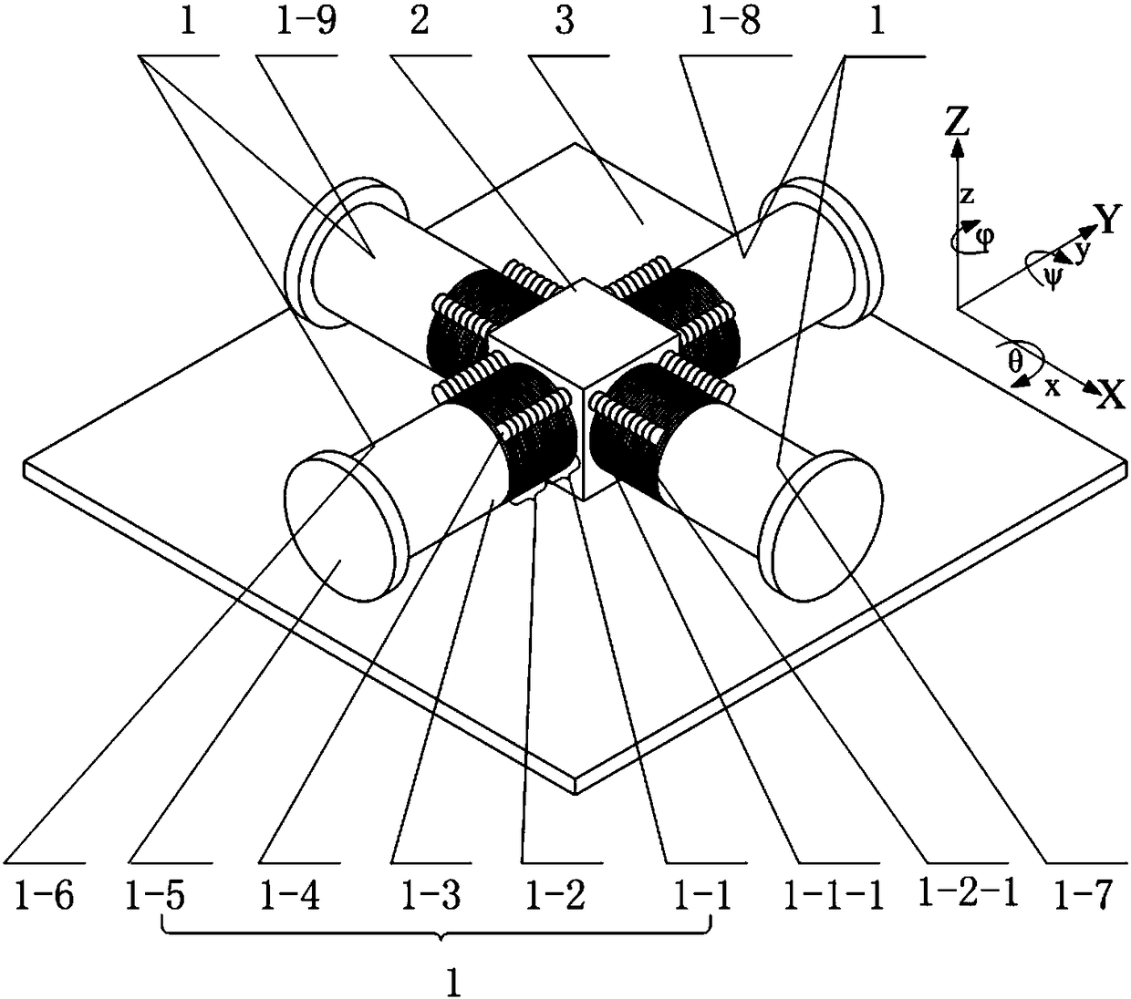
[0061] Specific implementation mode one: refer to figure 1 Specifically explain this embodiment, the six-degree-of-freedom piezoelectric drive device described in this embodiment includes four sets of piezoelectric vibrators 1, a base 2 and a table 3,
[0062] The four groups of piezoelectric vibrators 1 have the same structure, and each group of piezoelectric vibrators 1 includes a horizontally curved piezoelectric ceramic group 1-1, a vertically curved piezoelectric ceramic group 1-2, and a front end cover 1-3,
[0063] The head end of the ceramic group composed of the horizontally curved piezoelectric ceramic group 1-1 and the vertically curved piezoelectric ceramic group 1-2 is connected to the four sides of the base body 2 through threads, and the horizontally curved piezoelectric ceramic group 1-1 and the vertical The end of the ceramic group composed of bending piezoelectric ceramic groups 1-2 is connected to a front end cover 1-3, and the end of the front end cover 1-3...
specific Embodiment approach 2
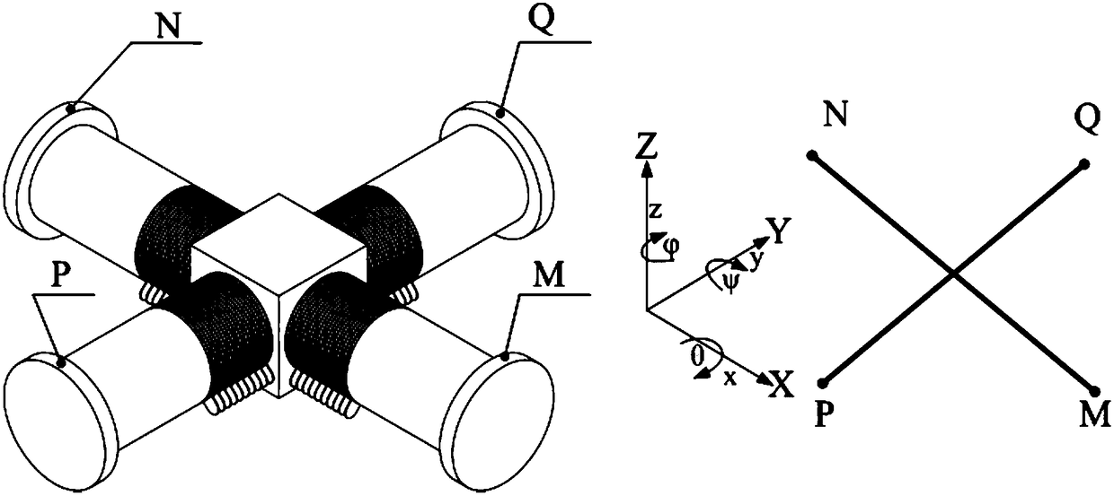
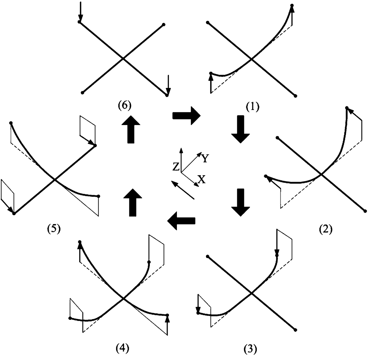
[0073] Specific implementation mode two: refer to Figure 2 to Figure 8 Describe this embodiment in detail. This embodiment is an excitation method for a six-degree-of-freedom piezoelectric drive device. This method is realized based on the six-degree-of-freedom piezoelectric drive device described in Embodiment 1. In this embodiment, the method can The six-degree-of-freedom piezoelectric driving device is driven to realize six-degree-of-freedom motion, wherein the six-degree-of-freedom includes movement along X, Y and Z axes, and rotation around X, Y and Z axes.
[0074] attached figure 2 A simplified schematic diagram of a six-degree-of-freedom piezoelectric drive device is given. In order to describe the motion trajectory of a six-degree-of-freedom piezoelectric drive device in one cycle, we simplify the piezoelectric vibrator 1 into a straight line. At the same time, we select four driving legs 1 -5 and the four contact points M, N, P, and Q of the workbench 3, use the m...
specific Embodiment approach 3
[0113] Specific implementation mode three: refer to Figure 9 Describe this embodiment in detail. This embodiment is an excitation method for a piezoelectric drive device with degrees of freedom. This method is realized based on the six-degree-of-freedom piezoelectric drive device described in the first specific embodiment. The excitation method for exciting the six-degree-of-freedom piezoelectric drive device to move along the X and Y axes, to excite it to move in any direction in the horizontal plane, and to move along the X and Y axes in the positive direction to realize the in-plane movement specifically includes the following steps:
[0114] Step 41. Apply a positive voltage to the vertically curved ceramic group 1-2 of the first group of piezoelectric vibrators 1-6 and the third group of piezoelectric vibrators 1-8, and they bend forward along the Z axis to drive the first group of piezoelectric vibrators The driving feet 1-5 of the vibrator 1-6 and the third group of pi...
PUM
 Abstract
Description
Claims
Application Information
 - R&D
- Intellectual Property
- Life Sciences
- Materials
- Tech Scout
- Unparalleled Data Quality
- Higher Quality Content
- 60% Fewer Hallucinations
Browse by: Latest US Patents, China's latest patents, Technical Efficacy Thesaurus, Application Domain, Technology Topic, Popular Technical Reports.
© 2025 PatSnap. All rights reserved.Legal|Privacy policy|Modern Slavery Act Transparency Statement|Sitemap|About US| Contact US: help@patsnap.com


