
A method for separating and recovering flue gas in the post-combustion zonebr 2 Methods

A technology of separation recovery and post-combustion zone, which is applied in the field of inorganic bromine, can solve the problems of molecular sieve corrosion, molecular sieve regeneration trouble, loss, etc., and achieve the effect of strong corrosion resistance, low operation cost, and unified economic benefits

Active Publication Date: 2019-09-17
ZUNYI NORMAL COLLEGE
View PDF2 Cites 0 Cited by
  • Summary
  • Abstract
  • Description
  • Claims
  • Application Information

AI Technical Summary

Problems solved by technology

[0004] However, the adsorption separation method used in the above process has many shortcomings: the mechanism of activated carbon, molecular sieve, etc. to separate the pollutants in the flue gas is generally considered to be the selection of some gaseous molecules in the flue gas by means of van der Waals force on the inner surface of the microporous channel. sex adsorption
Due to Br 2 The boiling point is low (about 59 ° C), when the temperature is low, a small amount of Br in the flue gas 2 It is easy to condense and precipitate to block the micropore channel of the adsorbent, reduce the adsorption area and reduce the adsorption efficiency
In addition, molecular sieves and activated carbon are expensive (usually several thousand yuan / ton to tens of thousands of yuan / ton); heavy, inconvenient to transport and operate; activated carbon and molecular sieve regeneration is troublesome and costly; , HCl and flue gas cooling process may form hydrobromic acid, hypobromous acid, acid formed by sulfur oxides and other corrosion, so there is some loss in actual use
Discarded molecular sieves are not easy to recycle and dispose of
Relevant documents (and patents) have not seen other separation and recovery of Br in flue gas 2 report

Method used


Image

  • A method for separating and recovering flue gas in the post-combustion zonebr  <sub>2</sub> Methods
  • A method for separating and recovering flue gas in the post-combustion zonebr  <sub>2</sub> Methods

Examples


Embodiment Construction

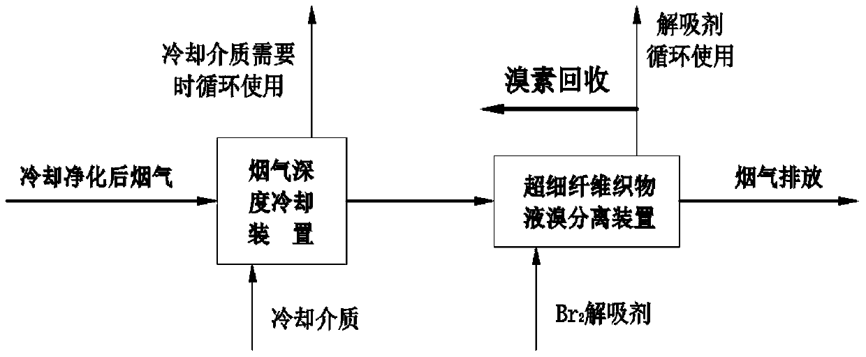
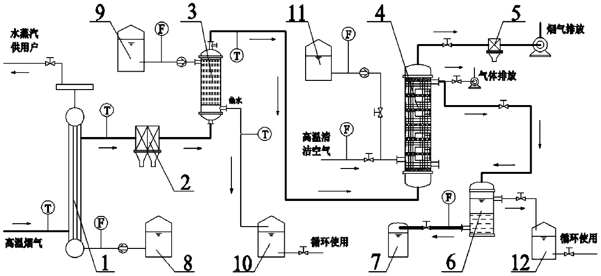
[0027] The present invention will be further described in detail below in conjunction with the accompanying drawings and embodiments.

[0028] Process flow diagram of the present invention is as figure 1 Shown, the equipment flow diagram of the present invention is as figure 2 shown. Bromine-containing high-temperature flue gas from the high-temperature combustion chamber and the second combustion chamber (about 1000-1400 °C; the raw material contains 6.5wt% Br, and the inorganic Br content in the flue gas is about 11g / Nm 3 ) enters the water-cooled two-stage cooling device 1 of indirect heat exchange, and is cooled to about 200°C in two stages (about 80% of the HBr in the flue gas is converted into Br 2 ), and then enter the flue gas purification device 2 to remove fly ash, NOx, etc. in the flue gas, and the purified flue gas passes through the flue gas deep cooling device 3 with indirect water cooling and heat exchange, and the temperature drops to about 28°C (the flue ga...


PUM


Abstract

The invention discloses a method for separating and recycling Br2 in flue gas in an after-burning area by using superfine fiber fabric. The method comprises steps like adsorption separation of the Br2 in the flue gas, desorption of adsorbed Br2 and separation of a desorption agent, and can finally obtain bromine. According to the invention, the principle of the superfine fiber fabric to adsorb the Br2 is different from the principle of a traditional adsorbent; the weight of adsorbed Br2 can be far beyond 30% of the weight of Br2; adsorption is performed at a low temperature, and the Br2 in the flue gas is easier to be extracted; the superfine fiber fabric material has strong corrosion resistance, so the service life is long, and less waste is generated in the process of application; and waste superfine fiber fabric can be treated by incineration. Compared with a traditional adsorption separation and recycling method, the method provided by the invention has high separation and recycling efficiencies and low operation cost, hardly generates new wastes, and realizes unity of environmental benefits and economic benefits.

Description

technical field [0001] The invention belongs to the technical field of energy and environmental protection engineering, and in particular relates to a method for separating an afterburning zone of a high-temperature combustion disposal system for bromine-containing substances and recovering inorganic bromine in flue gas. Background technique [0002] Environmental pollution and resource waste caused by electronic waste have attracted widespread attention from the government, scholars, and the public. Among the various disposal and recycling methods of waste printed circuit boards concerned by relevant research, compared with other methods, the pyrometallurgical process characterized by high-temperature combustion has the important advantage of high recovery rate of precious metals, and can effectively recover metal copper. , can achieve the maximum recycling of resources. However, due to the use of organic bromine series flame retardants, when waste printed circuit boards (...

Claims


Application Information

Patent Timeline
Patent Type & Authority Patents(China)
IPC IPC(8): B01D53/04C01B7/09
Inventor 肖菡曦蔡铁军邓谦彭荣华刘清泉
Owner ZUNYI NORMAL COLLEGE
Learn More