Stripping mold for small pipe fitting with closed end

A technology for small pipe fittings and demoulding, which is applied in the field of demoulding molds for small pipe fittings. It can solve problems such as unsmooth demoulding of products, groove scratches, and product stickiness, so as to avoid grooves from being strained and increase mold clamping. The trouble, the effect that is conducive to product production

Inactive Publication Date: 2017-06-23
泸州市胜科模具制造有限公司
View PDF5 Cites 3 Cited by
  • Summary
  • Abstract
  • Description
  • Claims
  • Application Information

AI Technical Summary

Problems solved by technology

[0004] The purpose of the present invention is to provide a demoulding mold for small pipe fittings with one end sealed, so as to solve the problem of products with glue on the top surface and a section of groove on the hole wall. Sliders and inclined tops cannot be used for demoulding, but core-pulling is directly used for demoulding. Not only will there be problems that the product will stick to the inclined roof and the product cannot be demoulded smoothly, but also the direct demoulding will cause the groove to be strained

Method used


Image

  • Stripping mold for small pipe fitting with closed end
  • Stripping mold for small pipe fitting with closed end
  • Stripping mold for small pipe fitting with closed end

Examples


Embodiment 1

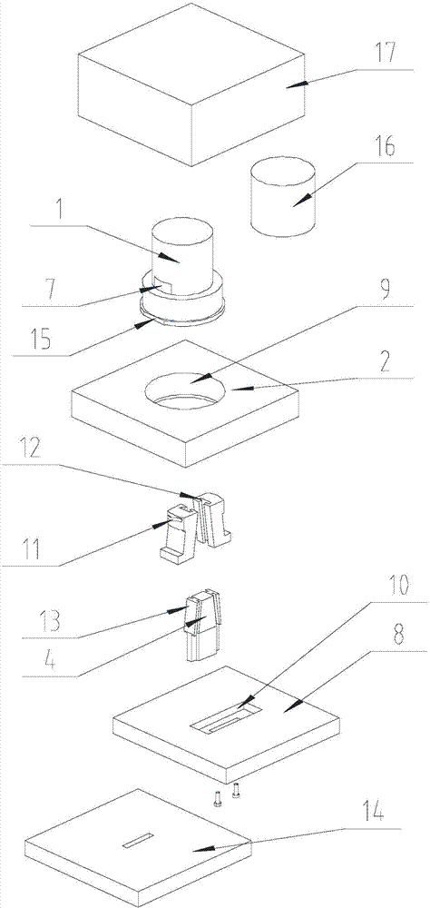
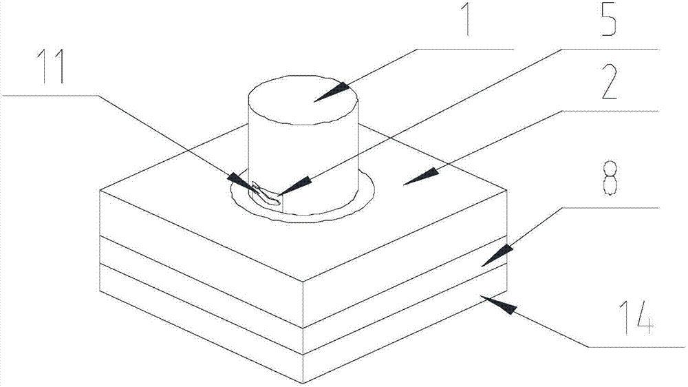
[0040] Such as Figure 1-Figure 10 Shown, label 16 among the figure is the product that glue is arranged on top surface; Label 17 is front mold. The demoulding mold for a small pipe with one end sealed in the present invention comprises a rear mold insert 1, a mounting plate 2, a limiting plate 8, a push assembly and a total block, and the rear mold insert 1 is cylindrical, and one end thereof is provided with The mounting groove 6 is provided with a matching hole 7 communicating with the bottom of the mounting groove 6 on the side of the rear mold insert 1. The total block includes a moving block 3 and a forming block 5 connected in sequence, and the forming block 5 is located in the matching In the hole 7, and the size of the forming block 5 is consistent with the size of the matching hole 7, and the surface of the forming block 5 away from the axis of the rear mold insert 1 is an arc-shaped surface with the same diameter as the side wall of the rear mold insert 1, that is, ...

Embodiment 2

[0047] The present invention is based on embodiment 1, and the present invention is further described.

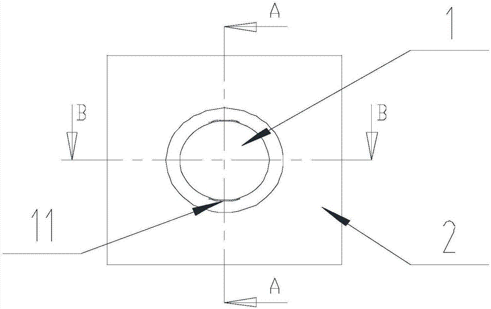
[0048] Such as Figure 1-Figure 10 As shown, the demoulding mold for small pipe fittings sealed at one end of the present invention, the installation groove 6 is coaxial with the rear mold insert 1, and the longitudinal section of the installation groove 6 is an isosceles trapezoid, and its small end communicates with the matching hole 7;

[0049] There are two matching holes 7 and the total block, and the matching holes 7 are symmetrically arranged on the side wall of the rear mold insert 1 along the axis of the rear mold insert 1, and the matching holes 7 are respectively matched with a total block;

[0050] The push assembly includes a tightening block 4 that is symmetrical along the axis of the rear mold insert 1, and the tightening block 4 is located between the general blocks and is in contact with the assembly block;

[0051] The projection of the axis of the rear m...

Embodiment 3

[0056] The present invention is based on embodiment 2, and the present invention is further described.

[0057] Such as Figure 1-Figure 10 As shown, the demoulding mold for small pipes with one end sealed in the present invention also includes a moving plate 14, and the end of the push assembly away from the rear mold insert 1 moves through the limit plate 8 and is located in the moving plate 14, and is passed through the bolt The push assembly is fixed on the moving plate 14. The bolts are countersunk head bolts.

[0058] During mold opening and mold closing, the movement of the tightening block 4 is driven by moving the moving plate 14, and the movement of the total block has been completed.


PUM


Abstract

The invention discloses a demoulding mold for a small pipe with one end sealed, comprising a rear mold insert, a mounting plate, a limiting plate, a push assembly and a total block, the rear mold insert is cylindrical, and an installation groove is arranged at one end thereof , the side of the rear mold insert is provided with a matching hole communicating with the bottom of the installation groove, the total block includes a moving block and a forming block connected in sequence, and the forming block is located in the matching hole; the arc of the forming block There is a groove forming part on the surface, the moving block is located in the installation groove; the pushing assembly is located in the installation groove, and contacts with the surface of the moving block close to the axis of the rear mold insert, and moves the pushing assembly, moving the block and forming The blocks are movable radially of the rear mold insert. This not only prevents the product from sticking to the mold and the product cannot be demoulded smoothly, but also avoids the situation that the groove is strained due to direct demoulding, which improves the product quality.

Description

technical field [0001] The invention relates to a mold, in particular to a demoulding mold for a small pipe with one end sealed. Background technique [0002] Mold, various molds and tools used in industrial production for injection molding, blow molding, extrusion, die-casting or forging forming, smelting, stamping and other methods to obtain the required products. In short, a mold is a tool used to shape an object. This tool is composed of various parts, and different molds are composed of different parts. It mainly realizes the processing of the shape of the article through the change of the physical state of the formed material. [0003] For some product parts with an outer diameter of less than 100mm, in order to cooperate with other parts, a groove will be provided on the wall of the central hole. At the same time, in order to facilitate the drafting after injection molding, the central hole is provided with a certain draft slope, so that the hole wall forms an angle...

Claims


Application Information

Patent Timeline
Patent Type & Authority Applications(China)
IPC IPC(8): B29C45/33B29C45/40
CPCB29C45/332B29C45/4005B29C2045/334
Inventor 唐应炳
Owner 泸州市胜科模具制造有限公司
Why Eureka
Try Eureka