Leg and foot structure of hydraulic-driven robot

A robot and driving technology, applied in the field of robot leg and foot structure, hydraulically driven robot leg and foot structure, can solve the problems of poor coordination performance of mechanical legs, uncoordinated movement, unfavorable motion control of biped mechanical legs, etc., to achieve Stable synergistic performance, stable driving mode, increased movement space and flexibility

Active Publication Date: 2017-06-23
BEIJING UNIV OF TECH
View PDF8 Cites 2 Cited by
  • Summary
  • Abstract
  • Description
  • Claims
  • Application Information

AI Technical Summary

Problems solved by technology

[0003] The existing mechanical leg design process mainly has the following problems: first, the coordination performance of the two mechanical legs is poor, and the two legs and feet cannot be coordinated in the process of ensuring standing and independently imitating people's "walking" process. ; Second, the continuous movement of the mechanical legs. The movement of the mechanical legs needs to be stable. Most of the existing open technical documents use fixed parts and connectors or multi-link mechanisms to ensure stability, but in the process of ensuring the movement of the mechanical legs The stability of the robot requires many control sources, and there is coupling between multiple control sources, which is not conducive to the motion control of the biped mechanical legs; third, the smooth and coordinated movement of the mechanical legs is generally driven by motors, and the weight of the motors generally needs to be equipped with balance weights , the weight of the balance weight is very critical to the load-bearing and stability of the mechanical leg itself

Method used


Image

  • Leg and foot structure of hydraulic-driven robot
  • Leg and foot structure of hydraulic-driven robot
  • Leg and foot structure of hydraulic-driven robot

Examples


Embodiment Construction

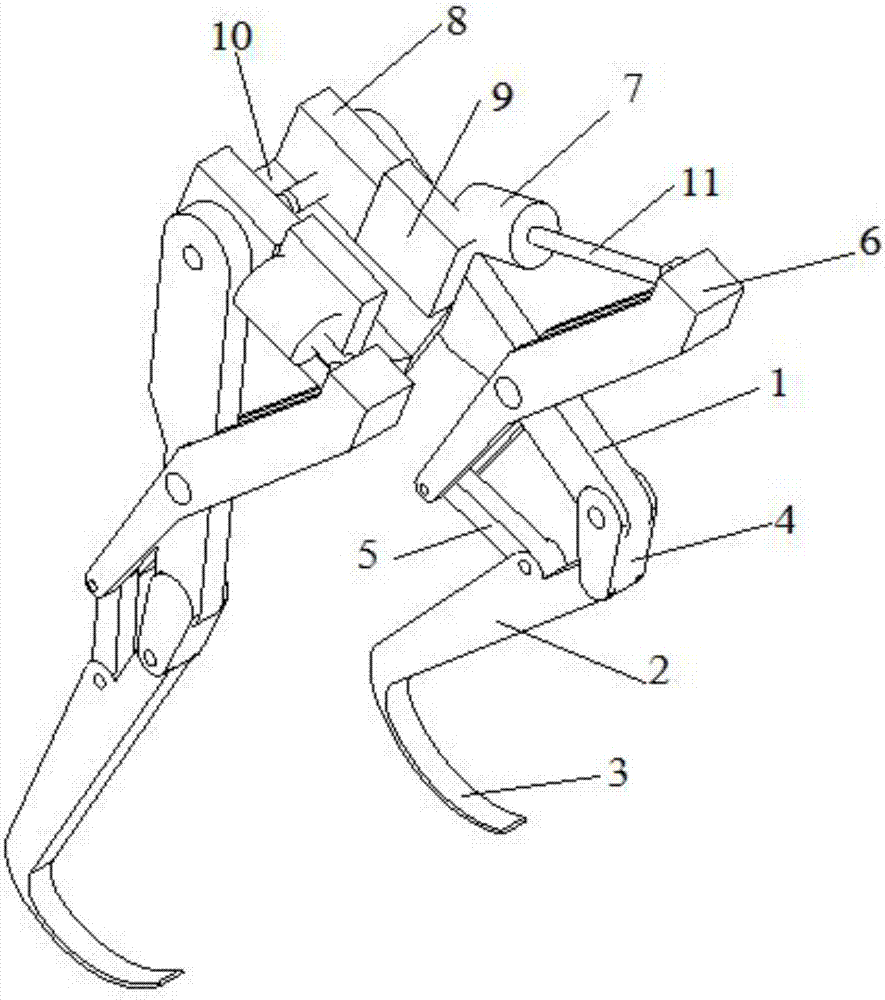
[0023] like figure 1 Shown is the overall structure of the leg and foot structure. The thigh piece 1 and the calf piece 2 are connected by the knee piece 4, and the bottom of the calf piece 2 is connected with a foot piece 3, and the foot piece 3 is welded on the bottom of the calf piece 2; between the thigh piece 1 and the knee piece 4 and between the knee piece 4 and the calf Parts 2 are all connected by pin shafts, and calf part 2 is connected with thigh part 1, calf part 2, foot part 3 and knee part 4 to form the main moving component of the robot; the main connecting part 6 and the receiving part 5 are auxiliary connections of the robot Adjusting piece; the main connecting piece 6 is provided with two pin holes, the first pin hole is set at the middle position of the main connecting piece 6, and the second pin hole is set at the bottom position of the main connecting piece 6; the main connecting piece 6 The top is connected with the hydraulic rod 11, the first pin hole o...


PUM


Abstract

The invention discloses a leg and foot structure of a hydraulic-driven robot and belongs to the technical field of robot manufacturing. A hydraulic system supplies oil to hydraulic cylinders. Piston parts of the hydraulic cylinders push hydraulic rods to move. The hydraulic rods push the front ends of main connecting pieces, the main connecting pieces rotate around pin shafts in the middle, carrying elements are stretched and drive shank parts to deflect, torque is generated at the joints of the shank parts and knee parts, the upper portions of the knee parts drive thigh parts to generate a forward moving tendency, the lower portions of the knee parts drive the shank parts to generate a backward moving tendency, the shank parts are matched with the carrying elements and the knee parts to generate backward friction force relative to the ground, foot parts connected with the shank parts are arc-shaped elements, and the arc-shaped elements rotate so that mechanical legs move forward. The two independent mechanical legs are independently driven by the hydraulic system to move forward.

Description

technical field [0001] The invention discloses a robot leg and foot structure, belongs to the technical field of robot manufacturing, and in particular relates to a hydraulically driven robot leg and foot structure. Background technique [0002] Existing walking robots attract people not because of their practicality, but because of their novelty, which is difficult to design after all. With the rapid development of science and technology, various design teams have developed various robots, and have made great achievements in imitating animals, but there is still a certain gap in the development of robots that can walk freely like humans. Much like animals evolve, robots will evolve to perfect their ability to walk, according to new computer simulations from the University of Vermont. [0003] The existing mechanical leg design process mainly has the following problems: first, the coordination performance of the two mechanical legs is poor, and the two legs and feet cannot ...

Claims


Application Information

Patent Timeline
Patent Type & Authority Applications(China)
IPC IPC(8): B62D57/032
CPCB62D57/032
Inventor 肖创柏姬庆庆刘鑫杨祎陈楠张洋张曼李兰君
Owner BEIJING UNIV OF TECH
Why Eureka
Try Eureka