Automatic silicon wafer feeding equipment

An automatic feeding and equipment technology, applied in the direction of conveyors, conveyor objects, transportation and packaging, etc., can solve the problems of intermittent feeding, high hardware cost, low efficiency, etc., to prevent overturning, save labor costs, and ensure effect of supply

Pending Publication Date: 2017-06-23
苏州卓樱自动化设备有限公司
View PDF6 Cites 5 Cited by
  • Summary
  • Abstract
  • Description
  • Claims
  • Application Information

AI Technical Summary

Problems solved by technology

[0004] Manual loading mode: It is necessary to manually transport the silicon wafers from the back of the cleaning machine to the designated storage area of ​​the loading table, take out the silicon wafers from the material frame, and perform operations that allow the operation of the corresponding loading module on the equipment. It is a purely manual operation, which is time-consuming and labor-intensive, and the efficiency is low
[0005] Manipulator loading mode: high hardware cost, large footprint, high post-maintenance costs, and high technical requirements
[0006] In the above two existing feeding modes, there are interruptions in sheet feeding when switching between feeding modules or switching between material frames, resulting in a short-term shortage of material in the rear-stage sorting equipment, which cannot fully exert its working efficiency

Method used


Image

  • Automatic silicon wafer feeding equipment
  • Automatic silicon wafer feeding equipment
  • Automatic silicon wafer feeding equipment

Examples


Embodiment Construction

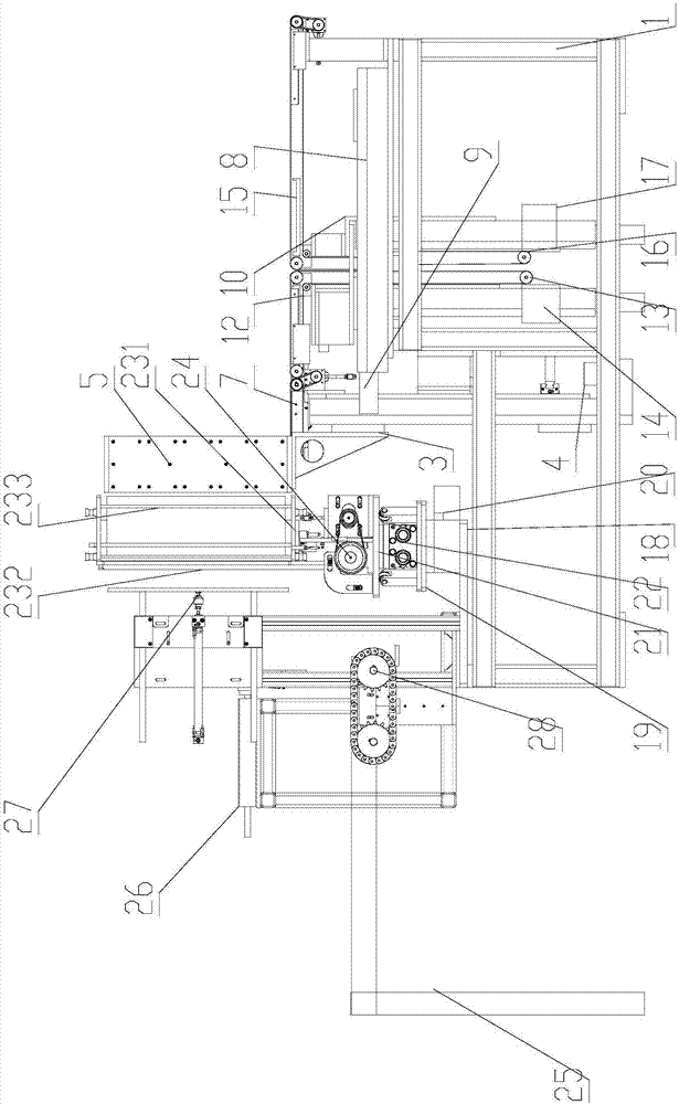
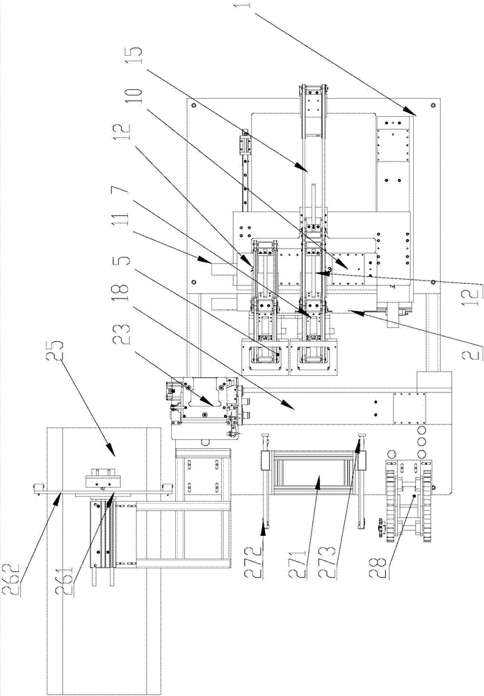
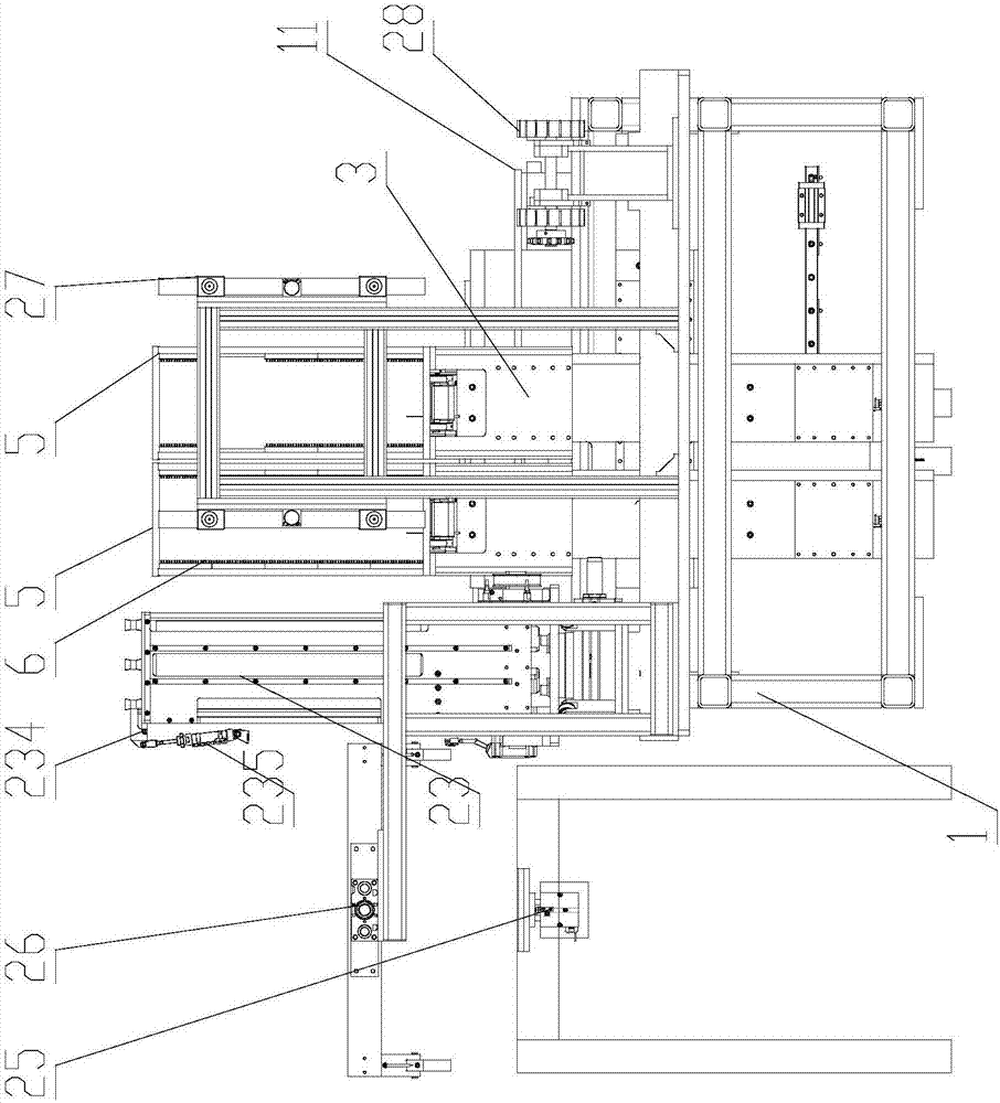
[0022] Specific embodiments of the present invention will be described in detail below in conjunction with the accompanying drawings.

[0023] like Figure 1-3 As shown, a kind of silicon wafer automatic feeding equipment comprises frame 1, and frame 1 is provided with the first sliding seat 2 and the first sliding driving device that drives first sliding seat 2 to slide back and forth, on the first sliding seat 2 There are two lifting platforms 3 arranged side by side along the moving direction of the first sliding seat 2 and two servo lifting drive mechanisms 4 that drive the lifting platform 3 to move up and down. The lifting platform 3 is provided with a storage frame 5, and the storage frame 5 There is a material rack 6 that arranges the sheet materials in parallel from top to bottom and has the same distance as the cloth in the material frame;

[0024] The first sliding seat 2 is provided with two material guide belt mechanisms 7 corresponding to the two material storag...


PUM


Abstract

The invention discloses automatic silicon wafer feeding equipment achieving unintermittent feeding. The automatic silicon wafer feeding equipment comprises a rack. A first sliding base and a first sliding driving device are arranged on the rack. Two lifting tables and two servo lifting driving mechanisms are arranged on the first sliding base. Material storage frames are arranged on the lifting tables. Two material guiding belt mechanisms are arranged on the first sliding base. A transition bottom plate which moves in the direction perpendicular to the sliding direction of the first sliding base and a transition driving device are arranged on the rack. A second sliding base and a second sliding driving device are arranged on the transition bottom plate. Two material conveying belt mechanisms are erected between the second sliding base and the first sliding base. A wafer conveying backstand is arranged on the transition bottom plate. A wafer discharging belt mechanism is erected between the transition bottom plate and the rack. A wafer outlet backstand is arranged on the transition bottom plate. The first sliding base and the second sliding base move synchronously to enable the two material conveying belt mechanisms to be in butt joint with the wafer discharging belt mechanism.

Description

technical field [0001] The invention relates to an automatic feeding device for silicon wafers. Background technique [0002] When silicon wafers enter the washing machine for cleaning, several silicon wafers need to be loaded side by side in the material frame. [0003] After the silicon wafers come out of the cleaning machine, the unqualified silicon wafers need to be sorted out by the subsequent sorting equipment. There are two modes of loading silicon wafers in the existing rear-end loading equipment: manual loading and large-scale gantry manipulator loading. [0004] Manual loading mode: It is necessary to manually transport the silicon wafers from the back of the cleaning machine to the designated storage area of ​​the loading table, take out the silicon wafers from the material frame, and perform operations that allow the operation of the corresponding loading module on the equipment. It belongs to pure manual operation, which is time-consuming, laborious and ineffi...

Claims


Application Information

Patent Timeline
Patent Type & Authority Applications(China)
IPC IPC(8): B65G47/74B65G47/52B65G23/44
CPCB65G23/44B65G47/52B65G47/74
Inventor 俞宗祥邹磊曹洪远陈根林
Owner 苏州卓樱自动化设备有限公司
Why Eureka
Try Eureka