Field visualization type strain sensor

A strain sensor, on-site technology, applied in the direction of electric/magnetic solid deformation measurement, electromagnetic measurement device, etc., can solve the problems of inability to classify alarms, inconvenient handling, easy loss, etc., achieve on-site early warning and remote control, and facilitate follow-up precision Effects for processing, easy transport and control

Inactive Publication Date: 2017-06-23
HUAZHONG UNIV OF SCI & TECH
View PDF8 Cites 6 Cited by
  • Summary
  • Abstract
  • Description
  • Claims
  • Application Information

AI Technical Summary

Problems solved by technology

In the existing sensor equipment, there are the following defects: (1) The existing strain monitoring process is very complicated, and it is necessary to attach the strain gauge first, and then connect the professional strain gauge to obtain the relevant results, and the strain gauge cannot be reused, and in It is inconvenient to paste in the construction environment, and the professional strain gauge is inconvenient to transport to the site because of its large volume and weight, and most of the workers on site do not know how to use the instrument, so they cannot tell whether the measured strain value belongs to the dangerous level; (2) the strain gauge The signal sensed by the strain gauge of the sensor is weak, and it is easy to be lost in the later processing process, resulting in insufficient early warning; (3) the existing strain sensor generally only realizes the alarm on site, and many engineering projects are in relatively remote areas , there may not be staff on site, therefore, even if there is an early warning, it may not be discovered in time; (4) the existing alarm system of the strain sensor can only alarm the dangerous situation, but cannot grade the alarm, resulting in the staff not being able to arrange suitable alarms in time. Countermeasures
In addition, the existing sensors also have disadvantages such as complex processing system and high cost

Method used


Image

  • Field visualization type strain sensor
  • Field visualization type strain sensor
  • Field visualization type strain sensor

Examples


Embodiment Construction

[0039] In order to make the object, technical solution and advantages of the present invention clearer, the present invention will be further described in detail below in conjunction with the accompanying drawings and embodiments. It should be understood that the specific embodiments described here are only used to explain the present invention, not to limit the present invention. In addition, the technical features involved in the various embodiments of the present invention described below can be combined with each other as long as they do not constitute a conflict with each other.

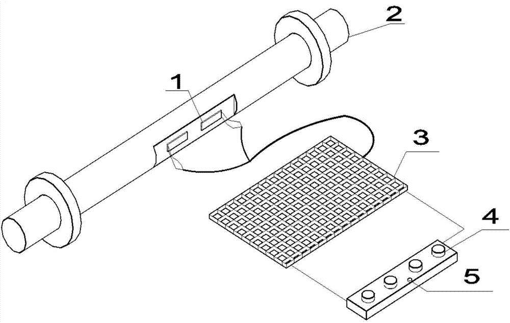
[0040] figure 1 It is a structural diagram of the strain sensor of the present invention, as shown in the figure, it includes elastic elements, strain gauges, circuit boards and on-site early warning devices,

[0041]Wherein, the elastic element is dumbbell-shaped, and the elastic element is fixed in the structure under test, and the strain gauge is the same as the surface shape of the elastic ...


PUM


Abstract

The invention belongs to the civil engineering monitoring equipment field and particularly relates to a field visualization type strain sensor, which comprises an elastic element, a strain gauge, a circuit board and a field early-warning device. The elastic element is fixed in a measured structure. The strain gauge is arranged on the surface of the elastic element. The strain gauge is connected with the circuit board. The deformation of the strain gauge is converted into an electrical signal and the electrical signal is transmitted to the circuit board. The circuit board is also connected with the field early-warning device. The circuit board includes a balanced bridge, a precise amplifier circuit, a signal processing module, an STM 32 single-chip microcomputer and a data transmission module. The invention also discloses an early-warning method based on the above strain sensor. According to the technical scheme of the invention, an alarm lamp is integrated with the sensor itself, and different colors of the alarm lamp correspond to different degrees of the structural deformation. Therefore, the engineering safety state is displayed in real time. The invention provides a real-time, in-situ and easily-understood engineering monitoring and early warning manner, wherein the field early-warning function and the remote control function are simultaneously realized. The early-warning effect is better.

Description

technical field [0001] The invention belongs to the field of civil engineering monitoring equipment, and more specifically relates to an on-site visualized strain sensor, which can detect dangerous situations in time, realize on-site and remote synchronous early warning, and can perform hierarchical warnings on dangerous situations. Background technique [0002] In large-scale construction engineering structures such as high-rise buildings, bridges, and tunnels, as time goes by, external environmental erosion, load action, and aging of its own materials will cause deformation and cracks in the body of the construction engineering structure. Monitoring and early warning of these deformations and cracks, and taking countermeasures as soon as possible can avoid the loss of personnel and property. In the existing sensor equipment, there are the following defects: (1) The existing strain monitoring process is very complicated, and it is necessary to attach the strain gauge first,...

Claims


Application Information

Patent Timeline
Patent Type & Authority Applications(China)
IPC IPC(8): G01B7/16
CPCG01B7/18
Inventor 刘华北徐东升宋思睿
Owner HUAZHONG UNIV OF SCI & TECH
Why Eureka
Try Eureka