
Light source arrangement method for RFID (radio frequency identification) tag automatic optical detection

An RFID label and automatic optical detection technology, which is applied in the field of RFID label detection, can solve the problems of imperfect detection items and the inability to detect the dirty detection of the inner bottom paper of INLAY, and achieve the effect of uniform image acquisition

Inactive Publication Date: 2017-06-23
ARIZON RFID TECH YANGZHOU
View PDF4 Cites 15 Cited by
  • Summary
  • Abstract
  • Description
  • Claims
  • Application Information

AI Technical Summary

Problems solved by technology

At present, there is no roll-to-roll RFID label testing equipment. The light source configuration of the existing optical testing equipment cannot detect the dirt inside the INLAY and the bottom paper surface. The testing items are not perfect, so it is difficult to meet the inspection needs of mass production.

Method used


Image

  • Light source arrangement method for RFID (radio frequency identification) tag automatic optical detection
  • Light source arrangement method for RFID (radio frequency identification) tag automatic optical detection

Examples


Embodiment Construction

[0026] The present invention will be further described below in conjunction with the accompanying drawings and description of the accompanying drawings.

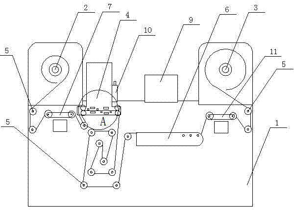
[0027] A light source configuration method for automatic optical detection of RFID tags, including a frame 1, on which a discharge reel 2, a rewinding reel 3, a visual detection device 4, several transmission wheels 5, a display 9, and a printer 10 are arranged. Wrap one end of the RFID label tape formed by a number of RFID tags on the release paper tape on the unwinding reel 2, and the other end passes through the visual inspection device 4 through several transmission wheels 5 and is wound on the rewinding reel 3; The detection device 8 includes a first detection device and a second detection device arranged horizontally at intervals.

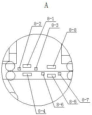
[0028] The first detection device comprises a front camera 8-1, a first left reflection light source 8-2, a first right reflection light source 8-3, a first transmission light source 8-4, a...


PUM


Abstract

The invention relates to a light source arrangement method for RFID (radio frequency identification) tag automatic optical detection. The method comprises a machine frame, wherein the machine frame is provided with an unreeling roll, a reeling roll, a visual detection device, a plurality of delivery wheels, a display device and an ink-jet printer, wherein one end of an RFID tag tape formed by bonding a plurality of RFID tags to a release paper tape is wound on the unreeling roll, and the other end penetrates through the visual detection device sequentially via the delivery wheels and is wound on the reeling roll; the visual detection device comprises a first detection device and a second detection device which are arranged horizontally at an interval; the first detection device comprises a front camera, a first left reflected light source, a first right reflected light source and a first transmitted light source; the second detection device comprises a back camera, a second left reflected light source, a second right reflected light source and a second transmitted light source; and the front camera and back camera are respectively connected with the display device through signal wires. The method is advanced and scientific; and the detection combination of the front and back sets and the visual solution of reflected light-transmitted light composite mode are utilized to effectively detect various types of defects in various materials.

Description

technical field [0001] The invention relates to a light source configuration method for automatic optical detection of RFID tags, belonging to the technical field of RFID tag detection. Background technique [0002] Automated Optical Inspection (AOI) is a new type of testing technology that is emerging. It is a device based on optical principles to detect common defects encountered in production. AOI uses a wealth of dedicated multi-functional detection algorithms and binary or gray-level optical imaging processing technology for detection. By using AOI as a tool for detecting defects, it can reduce manpower requirements, reduce dependence on personnel and improve inspection consistency. At present, there is no roll-to-roll RFID label testing equipment. The light source configuration of the existing optical testing equipment cannot detect the dirt inside the INLAY and the bottom paper surface. The testing items are not perfect, so it is difficult to meet the needs of mass p...

Claims


Application Information

Patent Timeline
Patent Type & Authority Applications(China)
IPC IPC(8): G01N21/89G01N21/94
CPCG01N21/89G01N21/8806G01N21/94G01N2021/8841
Inventor 袁正伟林向荣
Owner ARIZON RFID TECH YANGZHOU
Learn More